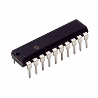
PIC24F04KA201-I/P Microchip Technology, PIC24F04KA201-I/P Datasheet - Page 5

PIC24F04KA201-I/P
Manufacturer Part Number
PIC24F04KA201-I/P
Description
IC PIC MCU FLASH 512KX4 20-PDIP
Manufacturer
Microchip Technology
Series
PIC® XLP™ 24Fr
Datasheets
1.PIC24F04KA201-ISS.pdf
(8 pages)
2.PIC24F04KA201-ISS.pdf
(48 pages)
3.PIC24F04KA201-ISS.pdf
(224 pages)
4.PIC24F04KA201-ISS.pdf
(26 pages)
Specifications of PIC24F04KA201-I/P
Core Size
16-Bit
Program Memory Size
4KB (1.375K x 24)
Peripherals
Brown-out Detect/Reset, HLVD, POR, PWM, WDT
Core Processor
PIC
Speed
32MHz
Connectivity
I²C, IrDA, SPI, UART/USART
Number Of I /o
18
Program Memory Type
FLASH
Ram Size
512 x 8
Voltage - Supply (vcc/vdd)
1.8 V ~ 3.6 V
Data Converters
A/D 9x10b
Oscillator Type
Internal
Operating Temperature
-40°C ~ 85°C
Package / Case
20-DIP (0.300", 7.62mm)
Controller Family/series
PIC24
No. Of I/o's
18
Ram Memory Size
512Byte
Cpu Speed
32MHz
No. Of Timers
3
Processor Series
PIC24F
Core
PIC
Data Bus Width
16 bit
Data Ram Size
512 B
Interface Type
I2C, SPI, UART
Maximum Clock Frequency
32 KHz
Number Of Programmable I/os
12
Number Of Timers
3
Operating Supply Voltage
1.8 V to 3.6 V
Maximum Operating Temperature
+ 125 C
Mounting Style
Through Hole
3rd Party Development Tools
52713-733, 52714-737, 53276-922, EWDSPIC
Development Tools By Supplier
PG164130, DV164035, DV244005, DV164005, DM240001
Minimum Operating Temperature
- 40 C
On-chip Adc
10 bit, 9 Channel
Lead Free Status / RoHS Status
Lead free / RoHS Compliant
Eeprom Size
-
Lead Free Status / Rohs Status
Details
8. Module: Core (Doze Mode)
TABLE 26-5:
2011 Microchip Technology Inc.
Standard Operating Conditions (unless otherwise stated)
Operating temperature
DC19
Note 1:
Param
No.
Operations that immediately follow any manipu-
lations of the DOZE<2:0> or DOZEN bits
(CLDIV<14:11>) may not execute properly. In
particular, for instructions that operate on an
SFR, data may not be read properly. Also, bits
automatically cleared in hardware may not be
cleared if the operation occurs during this
interval.
Work around
Always insert a NOP instruction before and after
either of the following:
•
•
Affected Silicon Revisions
A1
X
Sym
Enabling or disabling Doze mode by setting
or clearing the DOZEN bit
Before or after changing the DOZE<2:0> bits
LPBOR re-arms the POR circuit, but does not cause a BOR.
BOR Voltage on
V
DD
BOR TRIP POINTS
Transition
-40°C T
Characteristic
A
+85°C for industrial
BORV = 00
BORV = 01 2.92
BORV = 10 2.63
BORV = 11 1.75
PIC24F04KA201 FAMILY
Min
—
1.82 2.01
Typ
2.7
—
3
Data Sheet Clarifications
The following typographic corrections and clarifications
are to be noted for the latest version of the Device Data
Sheet (DS39937B):
1. Module: Electrical Specifications
Note:
Max
3.25
2.92
Table 26-5 (“BOR Trip Points”) has changed to
reflect the functionality of the LPBOR trip point
(BORV<1:0> = 00), and to make other typo-
graphic
maximum values for the BOR trip points in
Table 26-5 have changed. The new version of
the table is shown below (changes in bold).
—
Units
Corrections are shown in bold. Where
possible, the original bold text formatting
has been removed for clarity.
—
V
V
V
corrections.
(DC Specifications)
Note (1)
The
Conditions
minimum
DS80474B-page 5
and


