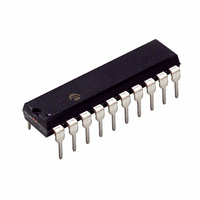
PIC24F04KA201-I/P Microchip Technology, PIC24F04KA201-I/P Datasheet - Page 3

PIC24F04KA201-I/P
Manufacturer Part Number
PIC24F04KA201-I/P
Description
IC PIC MCU FLASH 512KX4 20-PDIP
Manufacturer
Microchip Technology
Series
PIC® XLP™ 24Fr
Datasheets
1.PIC24F04KA201-ISS.pdf
(8 pages)
2.PIC24F04KA201-ISS.pdf
(48 pages)
3.PIC24F04KA201-ISS.pdf
(224 pages)
4.PIC24F04KA201-ISS.pdf
(26 pages)
Specifications of PIC24F04KA201-I/P
Core Size
16-Bit
Program Memory Size
4KB (1.375K x 24)
Peripherals
Brown-out Detect/Reset, HLVD, POR, PWM, WDT
Core Processor
PIC
Speed
32MHz
Connectivity
I²C, IrDA, SPI, UART/USART
Number Of I /o
18
Program Memory Type
FLASH
Ram Size
512 x 8
Voltage - Supply (vcc/vdd)
1.8 V ~ 3.6 V
Data Converters
A/D 9x10b
Oscillator Type
Internal
Operating Temperature
-40°C ~ 85°C
Package / Case
20-DIP (0.300", 7.62mm)
Controller Family/series
PIC24
No. Of I/o's
18
Ram Memory Size
512Byte
Cpu Speed
32MHz
No. Of Timers
3
Processor Series
PIC24F
Core
PIC
Data Bus Width
16 bit
Data Ram Size
512 B
Interface Type
I2C, SPI, UART
Maximum Clock Frequency
32 KHz
Number Of Programmable I/os
12
Number Of Timers
3
Operating Supply Voltage
1.8 V to 3.6 V
Maximum Operating Temperature
+ 125 C
Mounting Style
Through Hole
3rd Party Development Tools
52713-733, 52714-737, 53276-922, EWDSPIC
Development Tools By Supplier
PG164130, DV164035, DV244005, DV164005, DM240001
Minimum Operating Temperature
- 40 C
On-chip Adc
10 bit, 9 Channel
Lead Free Status / RoHS Status
Lead free / RoHS Compliant
Eeprom Size
-
Lead Free Status / Rohs Status
Details
Silicon Errata Issues
1. Module: Resets (BOR)
TABLE 3:
2011 Microchip Technology Inc.
Param
Note:
No.
A device Reset may occur if the BOR is disabled
and
(RCON<14> is cleared, and then immediately
set).
Work around
It is recommended that several NOP instructions
be added to a BOR disable/enable sequence.
Alternatively, place several instructions or a
short routine between the instructions to disable
and enable the BOR.
Affected Silicon Revisions
A1
X
V
Symbol
immediately
IOFF
This document summarizes all silicon
errata issues from all revisions of silicon,
previous as well as current. Only the
issues indicated by the shaded column in
the following tables apply to the current
silicon revision (A1).
COMPARATOR DC SPECIFICATIONS (PARTIAL)
Input Offset Voltage
re-enabled
Characteristics
in
software
PIC24F04KA201 FAMILY
Min
—
Typ
20
2. Module: Core (Deep Sleep)
3. Module: Comparator
Deep Sleep wake-up sources may be ignored if
they occur just prior to entry into Deep Sleep
mode. As a result, the device may enter Deep
Sleep mode when it should not.
Work around
If possible, configure external Deep Sleep
wake-up sources to repeat themselves once. If
the device does enter Deep Sleep, the second
occurrence of the wake-up source will wake the
device.
Alternatively, synchronize the entry into Deep
Sleep with external wake-up sources, where
possible.
Affected Silicon Revisions
The maximum value for the input offset voltage
(specification
Table 26-12 of the Device Data Sheet, has
changed for this silicon revision. The new value
is shown in
Work around
None.
Affected Silicon Revisions
Max
60
A1
A1
X
X
Units
mV
Table 3
D300,
(changes in bold).
V
IOFF
Comments
),
DS80474B-page 3
shown
in


