PIC18LF13K50-I/MQ Microchip Technology, PIC18LF13K50-I/MQ Datasheet - Page 22
PIC18LF13K50-I/MQ
Manufacturer Part Number
PIC18LF13K50-I/MQ
Description
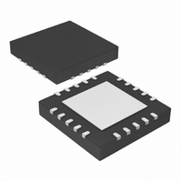
IC PIC MCU FLASH 512KX8 20-QFN
Manufacturer
Microchip Technology
Series
PIC® XLP™ 18Fr
Datasheets
1.PIC18F13K50-ISS.pdf
(420 pages)
2.PIC18F13K50-ISS.pdf
(40 pages)
3.PIC18F13K50-ISS.pdf
(10 pages)
4.PIC18F13K50-ISS.pdf
(2 pages)
5.PIC18F14K50-IP.pdf
(422 pages)
Specifications of PIC18LF13K50-I/MQ
Program Memory Type
FLASH
Program Memory Size
8KB (4K x 16)
Package / Case
20-QFN
Core Processor
PIC
Core Size
8-Bit
Speed
48MHz
Connectivity
I²C, SPI, UART/USART, USB
Peripherals
Brown-out Detect/Reset, POR, PWM, WDT
Number Of I /o
14
Eeprom Size
256 x 8
Ram Size
512 x 8
Voltage - Supply (vcc/vdd)
1.8 V ~ 3.6 V
Data Converters
A/D 11x10b
Oscillator Type
Internal
Operating Temperature
-40°C ~ 85°C
Processor Series
PIC18LF
Core
PIC
Data Bus Width
8 bit
Data Ram Size
512 B
Interface Type
EUSART/I2C/MSSP/SPI/USB
Maximum Clock Frequency
48 MHz
Number Of Programmable I/os
15
Number Of Timers
4
Operating Supply Voltage
1.8 V to 3.6 V
Maximum Operating Temperature
+ 85 C
Mounting Style
SMD/SMT
3rd Party Development Tools
52715-96, 52716-328, 52717-734, 52712-325, EWPIC18
Development Tools By Supplier
PG164130, DV164035, DV244005, DV164005, DM164127, DV164126
Minimum Operating Temperature
- 40 C
On-chip Adc
11-ch x 10-bit
Controller Family/series
PIC18
No. Of I/o's
15
Eeprom Memory Size
256Byte
Ram Memory Size
512Byte
Cpu Speed
48MHz
No. Of Timers
4
Lead Free Status / RoHS Status
Lead free / RoHS Compliant
Lead Free Status / RoHS Status
Lead free / RoHS Compliant, Lead free / RoHS Compliant
Available stocks
Company
Part Number
Manufacturer
Quantity
Price
Company:

Part Number:
PIC18LF13K50-I/MQ
Manufacturer:
MICROCHIP
Quantity:
2 400


PIC18F1XK50/PIC18LF1XK50
TABLE 4-9:
FIGURE 4-8:
DS41342E-page 22
Step 1: Direct access to config memory.
0000
0000
0000
Step 2
0000
0000
0000
0000
0000
0000
1111
0000
0000
0000
1111
0000
Note 1:
Command
4-bit
(1)
: Set Table Pointer for config byte to be written. Write even/odd addresses.
Enabling the write protection of Configuration bits (WRTC = 0 in CONFIG6H) will prevent further writing of
Configuration bits. Always write all the Configuration bits before enabling the write protection for Configuration bits.
<MSB ignored><LSB>
<MSB><LSB ignored>
SET ADDRESS POINTER TO CONFIGURATION LOCATION
Data Payload
CONFIGURATION PROGRAMMING FLOW
Delay P9 and P10
Time for Write
8E A6
8C A6
Configuration
84 A6
0E 30
6E F8
0E 00
6E F7
0E 00
6E F6
0E 01
6E F6
00 00
00 00
Load Even
Program
Address
Done
Start
LSB
BSF EECON1, EEPGD
BSF EECON1, CFGS
BSF EECON1, WREN
MOVLW 30h
MOVWF TBLPTRU
MOVLW 00h
MOVWF TBLPRTH
MOVLW 00h
MOVWF TBLPTRL
Load 2 bytes and start programming.
NOP - hold PGC high for time P9 and low for time P10.
MOVLW 01h
MOVWF TBLPTRL
Load 2 bytes and start programming.
NOP - hold PGC high for time P9A and low for time P10.
Advance Information
Core Instruction
Delay P9 and P10
Time for Write
Configuration
Load Odd
Program
Address
MSB
Start
Done
2010 Microchip Technology Inc.
Related parts for PIC18LF13K50-I/MQ
Image
Part Number
Description
Manufacturer
Datasheet
Request
R

Part Number:
Description:
Manufacturer:
Microchip Technology Inc.
Datasheet:
Part Number:
Description:
Manufacturer:
Microchip Technology Inc.
Datasheet:
Part Number:
Description:
Manufacturer:
Microchip Technology Inc.
Datasheet:
Part Number:
Description:
Manufacturer:
Microchip Technology Inc.
Datasheet:
Part Number:
Description:
Manufacturer:
Microchip Technology Inc.
Datasheet:
Part Number:
Description:
Manufacturer:
Microchip Technology Inc.
Datasheet:
Part Number:
Description:
Manufacturer:
Microchip Technology Inc.
Datasheet:
Part Number:
Description:
Manufacturer:
Microchip Technology Inc.
Datasheet: