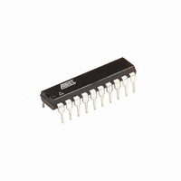
AT89LP4052-20PU Atmel, AT89LP4052-20PU Datasheet - Page 64

AT89LP4052-20PU
Manufacturer Part Number
AT89LP4052-20PU
Description
IC 8051 MCU FLASH 4K 20DIP
Manufacturer
Atmel
Series
89LPr
Datasheet
1.AT89LP2052-20PU.pdf
(94 pages)
Specifications of AT89LP4052-20PU
Core Processor
8051
Core Size
8-Bit
Speed
20MHz
Connectivity
SPI, UART/USART
Peripherals
Brown-out Detect/Reset, POR, PWM, WDT
Number Of I /o
15
Program Memory Size
4KB (4K x 8)
Program Memory Type
FLASH
Ram Size
256 x 8
Voltage - Supply (vcc/vdd)
2.4 V ~ 5.5 V
Oscillator Type
Internal
Operating Temperature
-40°C ~ 85°C
Package / Case
20-DIP (0.300", 7.62mm)
Processor Series
AT89x
Core
8051
Data Bus Width
8 bit
Data Ram Size
256 B
Interface Type
UART, SPI
Maximum Clock Frequency
20 MHz
Number Of Programmable I/os
15
Number Of Timers
2
Operating Supply Voltage
2.4 V to 5.5 V
Maximum Operating Temperature
+ 85 C
Mounting Style
Through Hole
3rd Party Development Tools
PK51, CA51, A51, ULINK2
Development Tools By Supplier
AT89ISP
Minimum Operating Temperature
- 40 C
Lead Free Status / RoHS Status
Lead free / RoHS Compliant
Eeprom Size
-
Data Converters
-
Lead Free Status / Rohs Status
Lead free / RoHS Compliant
23.4.6
64
AT89LP2052/LP4052
Write Code Page
Function:
Usage:
Note:
Figure 23-10. Write Code Page Sequence
Note:
• Programs 1 page (1 to 32 bytes) of data into the Code Memory array.
• Page address determined by bits [11:5] of loaded address.
• The byte address (offset in page) is initialized to bits [4:0] of the low address byte. One byte
1. Bring CS (P3.2) low.
2. Drive P1 to AAh and pulse XTAL1 high.
3. Drive P1 to 50h and pulse XTAL1 high.
4. Drive P1 with bits [15:8] of address and pulse XTAL1 high.
5. Drive P1 with bits [7:0] of address and pulse XTAL1 high.
6. To write only previously loaded data, bring CS high before loading additional bytes. To
7. Bring CS high.
8. Wait 2 ms, monitor P3.1, or poll data/status.
RDY/BSY
of data is loaded from P1 for the current address by the positive edge of a XTAL1 pulse. The
internal address is incremented by one on the negative edge of the XTAL1 pulse. The
address will wrap around to the 1st byte of the page when incremented past 31, however
previously loaded bytes should not be re-loaded.
XTAL1
load data bytes, drive data on P1 and pulse XTAL1 high to load one byte and increment
to the next address. Repeat for additional bytes. Only 1-32 bytes may be programmed
at one time, including any bytes loaded by a previous load page buffer command. Bytes
should not be loaded more than once.
CS
P1
It is not possible to skip bytes while loading data during write. To load non-contiguous bytes in a
page, use the Load Page Buffer command.
The waveform on this page is not to scale.
AAh
50h
0000aaaa aaabbbbb
DIN 0
DIN 1
DIN n
3547J–MICRO–10/09


