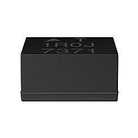
B82422T1473K EPCOS Inc, B82422T1473K Datasheet - Page 15

B82422T1473K
Manufacturer Part Number
B82422T1473K
Description
INDUCTOR 47UH 60MA 1210 10%
Manufacturer
EPCOS Inc
Series
SIMIDr
Type
Ferrite Corer
Specifications of B82422T1473K
Inductance
47µH
Tolerance
±10%
Package / Case
1210 (3225 Metric)
Current
60mA
Dc Resistance (dcr)
7 Ohm Max
Q @ Freq
27 @ 2.52MHz
Self Resonant Freq
15MHz
Mounting Type
Surface Mount
Frequency - Test
2.52MHz
Material - Core
Ferrite
Applications
General Purpose
Core Material
Ferrite
Dimensions
2.5 mm W x 3.2 mm L x 2.1 mm H
Shielding
Unshielded
Test Frequency
2.52 MHz
Maximum Dc Current
60 mAmps
Maximum Dc Resistance
7 Ohms
Self Resonant Frequency
15 MHz
Q Minimum
27
Termination Style
SMD/SMT
Inductance Tolerance
± 10%
Dc Resistance Max
7ohm
Dc Current Rating
60mA
Q Test Frequency
2.52MHz
Inductor Case Style
1210
No. Of Pins
2
Svhc
No SVHC
Rohs Compliant
Yes
Lead Free Status / RoHS Status
Lead free / RoHS Compliant
Current - Saturation
-
Current - Temperature Rise
-
Lead Free Status / Rohs Status
Lead free / RoHS Compliant
Other names
495-1738-2
B82422T1473K000
B82422T1473K000
7.8
The stray inductance L
both coils when a current-compensated choke is short-circuited at one end. This affects symmetri-
cal interference.
Fig. 11
7.9
The inductance decrease L / L
inductance L
crease is caused by the magnetization of the core material, which is a function of the field strength,
as induced by the operating current. Generally the decrease is less than 10 % .
7.10
The dc resistance is the resistance of a line as measured using direct current at a temperature of
20 C, whereby the measuring current must be kept well below the rated current.
R
R
R
7.11
Parasitic capacitances ( C
the component geometry. These capacitances may affect the two lines mutually (symmetrically) as
well as the line-to-ground circuit (asymmetrically). The design of all EMC components supplied by
EPCOS minimizes the parasitic effects. Due to this, these components have excellent interference
suppression characteristics right up to high frequencies.
7.12
The quality factor Q is the quotient of the imaginary component of the impedance divided by the real
component.
7.13
f
f
Q
L
General Technical Information
typ
min
max
is the frequency at which the inductance of a choke is determined.
is the frequency for which the quality factor Q of a choke is specified.
Stray inductance L
Inductance decrease L / L
DC resistance R
typical value
minimum value
maximum value
Winding capacitance, parasitic capacitance C
Quality factor Q
Measuring frequencies f
Stray inductance
0
measured at zero current. The data sheets specify this as a percentage. This de-
S
P
typ
(also termed leakage inductance) is the inductance measured through
), which impair the RF characteristics of the components, are related to
, R
S
0
min
is the drop in inductance at a given current relative to the initial
, R
Q
, f
0
max
L
23
04/00
P


