4120-G111-K1M1-A2S0ZN-15A E-T-A, 4120-G111-K1M1-A2S0ZN-15A Datasheet - Page 3
4120-G111-K1M1-A2S0ZN-15A
Manufacturer Part Number
4120-G111-K1M1-A2S0ZN-15A
Description
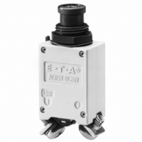
THERMAL CIRC BREAKER 15A 28VDC
Manufacturer
E-T-A
Series
4120r
Datasheet
1.4120-G111-K1M1-A2S0ZN-15A.pdf
(4 pages)
Specifications of 4120-G111-K1M1-A2S0ZN-15A
Breaker Type
Thermal
Voltage
28VDC, 115VAC
Current - Trip (it)
15A
Number Of Poles
1
Actuator Type
Push-Pull Plunger
Mounting Type
Panel Mount
Lead Free Status / RoHS Status
Lead free / RoHS Compliant
Other names
4120-G111-K1M1-A2S0ZN-15AMP
Q2330575
Q2330575


Issue B
Mounting holes
Other terminal designs
Terminal distances to:
MS 14 105 (a, b)
MS 14 153 (a, b)
MS 22 073 (a)
MS 22 074 (a)
MS 25 244 (a)
MS 25 373 (a, b)
Terminal design -P1
4120-G2...
.126
4120-G1...
.126
Terminal design -J2
Terminal design -J3
Terminal distances to:
MS 26 574 (a, b)
ø3,2
ø3,2
+.006
+.006
+0,15
+0,15
thickness:
1.5 - 3 mm
.059 - .118 in.
thickness:
1.5 - 3 mm
.059 - .118 in.
High Performance Thermal Circuit Breaker 4120-...
(18 mm/.709 in.)
(15 mm/.591 in.)
mounting holes S0
mounting holes S1 or S5
* min. 25 mm / .984 in. when fitted with splash cover
min. 20
min. 25 *
min .787
min .984 *
ø12.5
ø12.5
min. 20
min. 25 *
min .787
min .984 *
.492
.492
.512
13
+.008
+.008
a
+0.2
+0.2
a
.118
.138
ø3.5
ø3
±.004
+0.1
±.004
+0.1
thickness 1.5 - 3 mm
thickness 1.5 - 3 mm
10.5
.413
.335
8.5
.059 - .118 in.
.059 - .118 in.
.248
6.3
www.e-t-a.com
This is a metric design and millimeter dimensions take precedence ( mm )
Internal connection diagram
Typical time/current characteristics
with auxiliary contact
EN 2995-004
10000
0.001
1000
0.01
100
0.1
10
1
1
line 1
line 1
2
2
2
… times rated current
4 6 810
3
4
20
with polarized auxiliary contact
EN 2995-005
40
with auxiliary contact
VG 95345 T06
6080100
line 1
line 1
2
2
inch
11
12
3
5
+73.4 °F
+125°C
+257°F
+23 °C
-55°C
-67°F
4 - 47
4
Related parts for 4120-G111-K1M1-A2S0ZN-15A
Image
Part Number
Description
Manufacturer
Datasheet
Request
R

Part Number:
Description:
THERMAL CIRCUIT BREAKR 15A 28VDC
Manufacturer:
E-T-A
Datasheet:

Part Number:
Description:
CIRCUIT PROTECTOR; 10 A CLASS I, DIVISION 2 ; RESET INPUT AND STATUS OUTPUT ; 24
Manufacturer:
E-T-A Circuit Protection and Control
Datasheet:
Part Number:
Description:
Circuit Breaker; Therm; Push; Cur-Rtg 2A; PCB; 1 Pole; Vol-Rtg 240/28VAC/VDC
Manufacturer:
E-T-A Circuit Protection and Control
Datasheet:
Part Number:
Description:
Circuit Breaker; Therm; Push; Cur-Rtg 8A; Panel/PCB; 1 Pole; Vol-Rtg 240/28VAC/VDC
Manufacturer:
E-T-A Circuit Protection and Control
Datasheet:
Part Number:
Description:
Circuit Breaker; Therm; Push; Cur-Rtg 1A; Panel/PCB; 1 Pole; Vol-Rtg 240/28VAC/VDC
Manufacturer:
E-T-A Circuit Protection and Control
Datasheet:
Part Number:
Description:
Circuit Breaker; Therm; Push; Cur-Rtg 1.5A; Panel/PCB; 1 Pole; Vol-Rtg 240/28VAC/VDC
Manufacturer:
E-T-A Circuit Protection and Control
Datasheet:
Part Number:
Description:
Circuit Breaker; Therm; Push; Cur-Rtg 2A; Panel/PCB; 1 Pole; Vol-Rtg 240/28VAC/VDC
Manufacturer:
E-T-A Circuit Protection and Control
Datasheet:
Part Number:
Description:
Circuit Breaker; Therm; Push; Cur-Rtg 3.15A; Panel/PCB; 1 Pole; Vol-Rtg 240/28VAC/VDC
Manufacturer:
E-T-A Circuit Protection and Control
Datasheet:
Part Number:
Description:
Circuit Breaker; Therm; Push; Cur-Rtg 6.3A; Panel/PCB; 1 Pole; Vol-Rtg 240/28VAC/VDC
Manufacturer:
E-T-A Circuit Protection and Control
Datasheet:
Part Number:
Description:
Circuit Breaker; Therm; Push; Cur-Rtg 2.5A; Panel/PCB; 1 Pole; Vol-Rtg 240/28VAC/VDC
Manufacturer:
E-T-A Circuit Protection and Control
Datasheet:
Part Number:
Description:
Circuit Breaker; Therm; Push; Cur-Rtg 3.15A; PCB; 1 Pole; Vol-Rtg 240/28VAC/VDC
Manufacturer:
E-T-A Circuit Protection and Control
Datasheet:
Part Number:
Description:
Circuit Breaker; Therm; Push; Cur-Rtg 5A; PCB; 1 Pole; Vol-Rtg 240/28VAC/VDC
Manufacturer:
E-T-A Circuit Protection and Control
Datasheet:

Part Number:
Description:
CIRCUIT BREAKER VERT PCB 8A
Manufacturer:
E-T-A
Datasheet:
Part Number:
Description:
CIRCUIT BREAKER VERT PCB 5A
Manufacturer:
E-T-A
Datasheet:
Part Number:
Description:
Circuit Breaker, Single Pole, 250VAC 48 VDC, 0.05A
Manufacturer:
E-T-A Circuit Protection & Control