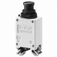
Single pole, miniaturised thermal circuit breaker with trip-free mechanism
and push/pull on/off manual actuation (M-type TO CBE to EN 60934).
Threadneck panel mounted, temperature-compensated, with optional
auxiliary contacts. Fully approved for commercial aircraft and similar
requirements.
Extra low voltage wiring systems on all types of vehicles for land, sea
and air.
Type No.
4120 - G 1 1 1 - K1 M1 - A 1 S0 Z N - 10 A
Issue B
4120
Description
Typical applications
Ordering information
single pole, with temperature compensation
Mounting
G
L
threadneck panel mounting
threadneck panel mounting, extended push button
Threadneck design
1
2
M12x1x6.3 (aluminium)
7/16-32 UNx6.3 (aluminium)
Number of poles
1
1-pole, thermally protected
Hardware for threadneck
0
1
2
3
4
without hardware
hex nut M12x1, corrugated washer 12/15, fitted
hex nut M12x1 (aluminium), serrated lock washer 12.1/17.2,fitted
hex nut M12x1 (aluminium), serrated lock washer 12.1/17.2, bulk shipped
hex nut 7/16-32UN (aluminium), serrated lock washer 11.3/14.9, fitted
Terminal design (main terminals)
K1
J1
J2
J3
P1
High Performance Thermal Circuit Breaker 4120-...
screw terminals with metric thread K14 (M4)
screw terminals with inch thread J14 (8-32UNC-2B)
screw terminals with inch thread J17 (8-32UNC-2B)
screw terminals with inch thread J25 (6-32UNC-2B)
blade terminals 6.3x0.8, DIN 46244, silver-plated
Characteristic curve
M1
thermal, 1.15 - 1.38 I
Terminal screws
A
B
C
D
K
M
Z
Phillips screw M4x6, fitted
Phillips screw 8-32UNC-2Ax6, fitted
Phillips screw 6-32UNC-2Ax6 (MS 51957-26)
slotted flat head screw M4x6, fitted
hex screw with Phillips head 8-32UNC-3Ax7.6, fitted
hex screw with Phillips head 8-32UNC-
3Ax7.6, bulk shipped
without terminal hardware
Terminal washers
0
1
2
4
5
6
without lock washer
wave washer B4, fitted
lock washer 4.3, fitted
lock washer 3.7 (MS 35338-136)
lock washer 4.3/9, fitted
lock washer 4.3/9, bulk shipped
Auxiliary contact
S0
S1
S5
without auxiliary contact
with auxiliary contact (connector
EN 3155-016M2018) (NC)
with polarized auxiliary contact (NC)
Barrier
Z
U
without barrier
with barrier (19.5 wide)
Colour of the push button
G
N
S
X
black, with white marking (e. g. 2.5)
black, without marking
green to EN (e. g. 2 1/2)
black to EN (e. g. 2 1/2)
Current ratings
1...25 A
N
ordering example
www.e-t-a.com
Dielectric strength
(IEC 60664 and 60664A)
Degree of protection
Corrosion
Humidity
Voltage rating
Current rating range
Auxiliary circuit
Typical life
Ambient temperature
Insulation co-ordination
(IEC 60664 and 60664A)
Insulation resistance
Interrupting capacity I
(IEC 60529/DIN 40050)
Vibration
(sinusoidal)
Vibration
Acceleration
Shock
Explosion
Altitude
Mass
Technical data
operating area
main to aux. circuit
cn
AC 115 V (400 Hz); DC 28 V
1...25 A (0.5 A upon request)
1 A, DC 28 V (0.5 A upon request)
20,000 operations mechanical, or
5,000 operations at 1 x I
-55°C ...+125°C (-67...+257 °F)
rated impulse
withstand voltage
1.5 kV
test voltage
AC 1,500 V
AC 1,500 V
> 100 MΩ (DC 500 V)
AC 115 V (400 Hz): 1...4 A
DC 28 V:
operating area IP40
terminal area IP00
10 g (57-2000 Hz), ± 0.76 mm (5-57 Hz)
to ISO 7137, EN 2350 para. 5.3.1
1...2.5 A: 0.04 g
3...20 A: 0.06 g
to ISO 7137, EN 2350 para. 5.3.1
17 g, to ISO 2669, EN 2350 para. 5.3.3
50 g (11 ms), to ISO 7137,
EN 2350 para. 5.3.2
48 hours at 5 % salt mist
to ISO 7137, EN 2350 para. 5.4.2
240 hours at 95 % RH,
to ISO 7137, EN 2350 para. 5.4.3
to VG 95210, sheet 10
≤ 22,000 m above sea level
approx. 20.6 g with terminal screws,
approx. 24.6 g with terminal screws,
4120-...
2
without -Si
with -Si
2
/Hz ± 1,5 dB; 9 g eff
/Hz ± 1,5 dB; 7.3 g eff
5...25 A
1...25 A
pollution
degree
3
N
1,000 A
2,000 A
6,000 A
4 - 45
4