TV04A640JB-G Comchip Technology, TV04A640JB-G Datasheet - Page 5
TV04A640JB-G
Manufacturer Part Number
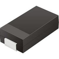
TV04A640JB-G
Description
TVS 400W 64V BIDIRECT SMA
Manufacturer
Comchip Technology
Specifications of TV04A640JB-G
Voltage - Reverse Standoff (typ)
64V
Voltage - Breakdown
71.1V
Power (watts)
400W
Polarization
Bidirectional
Mounting Type
Surface Mount
Package / Case
DO-214AC, SMA
Channels
1 Channel
Clamping Voltage
103 V
Operating Voltage
3.5 V
Breakdown Voltage
71.1 V
Peak Surge Current
40 A
Peak Pulse Power Dissipation
400 W
Lead Free Status / RoHS Status
Lead free / RoHS Compliant


Figures
September 8, 2009 S25FL128P_00_08
Figure 2.1
Figure 2.2
Figure 6.1
Figure 6.2
Figure 7.1
Figure 11.1
Figure 11.2
Figure 11.3
Figure 11.4
Figure 11.5
Figure 11.6
Figure 11.7
Figure 11.8
Figure 11.9
Figure 11.10 Read Status Register (RDSR) Command Sequence . . . . . . . . . . . . . . . . . . . . . . . . . . . . . . 27
Figure 11.11 Parallel Read Status Register (RDSR) Instruction Sequence . . . . . . . . . . . . . . . . . . . . . . . .28
Figure 11.12 Write Status Register (WRSR) Command Sequence . . . . . . . . . . . . . . . . . . . . . . . . . . . . . . 29
Figure 11.13 Parallel Write Status Register (WRSR) Command Sequence . . . . . . . . . . . . . . . . . . . . . . . . 29
Figure 11.14 Page Program (PP) Command Sequence. . . . . . . . . . . . . . . . . . . . . . . . . . . . . . . . . . . . . . . 31
Figure 11.15 Parallel Page Program (PP) Instruction Sequence . . . . . . . . . . . . . . . . . . . . . . . . . . . . . . . . 32
Figure 11.16 Sector Erase (SE) Command Sequence . . . . . . . . . . . . . . . . . . . . . . . . . . . . . . . . . . . . . . . . 33
Figure 11.17 Bulk Erase (BE) Command Sequence. . . . . . . . . . . . . . . . . . . . . . . . . . . . . . . . . . . . . . . . . . 34
Figure 11.18 Deep Power Down (DP) Command Sequence . . . . . . . . . . . . . . . . . . . . . . . . . . . . . . . . . . . 35
Figure 11.19 Release from Deep Power Down (RES) Command Sequence . . . . . . . . . . . . . . . . . . . . . . . 36
Figure 11.20 Serial Release from Deep Power Down and
Figure 11.21 Parallel Release from Deep Power Down and
Figure 12.1
Figure 13.1
Figure 13.2
Figure 15.1
Figure 15.2
Figure 18.1
Figure 19.1
Figure 19.2
Figure 19.3
Figure 19.4
16-pin Plastic Small Outline Package (SO) . . . . . . . . . . . . . . . . . . . . . . . . . . . . . . . . . . . . . . . 8
Read Data Bytes (READ) Command Sequence . . . . . . . . . . . . . . . . . . . . . . . . . . . . . . . . . . 19
Parallel Read Instruction Sequence. . . . . . . . . . . . . . . . . . . . . . . . . . . . . . . . . . . . . . . . . . . . 20
Parallel Read_ID Command Sequence and Data Out Sequence . . . . . . . . . . . . . . . . . . . . . 23
Read Electronic Signature (RES) Command Sequence . . . . . . . . . . . . . . . . . . . . . . . . . . . . .37
Read Electronic Signature (RES) Command Sequence . . . . . . . . . . . . . . . . . . . . . . . . . . . . .37
Maximum Negative Overshoot Waveform . . . . . . . . . . . . . . . . . . . . . . . . . . . . . . . . . . . . . . . 40
Maximum Positive Overshoot Waveform . . . . . . . . . . . . . . . . . . . . . . . . . . . . . . . . . . . . . . . . 41
Write Protect Setup and Hold Timing during WRSR when SRWD=1 . . . . . . . . . . . . . . . . . . 45
8-Pin WSON Package (6 x 8 mm) . . . . . . . . . . . . . . . . . . . . . . . . . . . . . . . . . . . . . . . . . . . . . . 8
Bus Master and Memory Devices on the SPI Bus . . . . . . . . . . . . . . . . . . . . . . . . . . . . . . . . . 11
SPI Modes Supported . . . . . . . . . . . . . . . . . . . . . . . . . . . . . . . . . . . . . . . . . . . . . . . . . . . . . . 11
Hold Mode Operation. . . . . . . . . . . . . . . . . . . . . . . . . . . . . . . . . . . . . . . . . . . . . . . . . . . . . . . 14
Read Data Bytes at Higher Speed (FAST_READ) Command Sequence . . . . . . . . . . . . . . . 21
Read Identification Command Sequence and Data Out Sequence. . . . . . . . . . . . . . . . . . . . 22
Serial READ_ID Instruction Sequence . . . . . . . . . . . . . . . . . . . . . . . . . . . . . . . . . . . . . . . . . 24
Parallel Read_ID Instruction Sequence . . . . . . . . . . . . . . . . . . . . . . . . . . . . . . . . . . . . . . . . . 25
Write Enable (WREN) Command Sequence . . . . . . . . . . . . . . . . . . . . . . . . . . . . . . . . . . . . . 25
Write Disable (WRDI) Command Sequence . . . . . . . . . . . . . . . . . . . . . . . . . . . . . . . . . . . . . 26
ACC Program Acceleration Timing Requirements . . . . . . . . . . . . . . . . . . . . . . . . . . . . . . . . .38
Power-Up Timing Diagram. . . . . . . . . . . . . . . . . . . . . . . . . . . . . . . . . . . . . . . . . . . . . . . . . . . 39
Power-down and Voltage Drop . . . . . . . . . . . . . . . . . . . . . . . . . . . . . . . . . . . . . . . . . . . . . . . 39
AC Measurements I/O Waveform . . . . . . . . . . . . . . . . . . . . . . . . . . . . . . . . . . . . . . . . . . . . . 42
SPI Mode 0 (0,0) Input Timing . . . . . . . . . . . . . . . . . . . . . . . . . . . . . . . . . . . . . . . . . . . . . . . . 44
SPI Mode 0 (0,0) Output Timing . . . . . . . . . . . . . . . . . . . . . . . . . . . . . . . . . . . . . . . . . . . . . . 44
HOLD# Timing . . . . . . . . . . . . . . . . . . . . . . . . . . . . . . . . . . . . . . . . . . . . . . . . . . . . . . . . . . . . 45
D a t a
S h e e t
S25FL128P
5
Related parts for TV04A640JB-G
Image
Part Number
Description
Manufacturer
Datasheet
Request
R

Part Number:
Description:
Manufacturer:
Comchip Technology Corporation
Datasheet:
Part Number:
Description:
Manufacturer:
Comchip Technology Corporation
Datasheet:
Part Number:
Description:
Manufacturer:
Comchip Technology Corporation
Datasheet:
Part Number:
Description:
Manufacturer:
Comchip Technology Corporation
Datasheet:
Part Number:
Description:
Manufacturer:
Comchip Technology Corporation
Datasheet:
Part Number:
Description:
Manufacturer:
Comchip Technology Corporation
Datasheet:
Part Number:
Description:
Manufacturer:
Comchip Technology Corporation
Datasheet:
Part Number:
Description:
Manufacturer:
Comchip Technology Corporation
Datasheet:
Part Number:
Description:
Manufacturer:
Comchip Technology Corporation
Datasheet:
Part Number:
Description:
Manufacturer:
Comchip Technology Corporation
Datasheet:
Part Number:
Description:
Manufacturer:
Comchip Technology Corporation
Datasheet:
Part Number:
Description:
Manufacturer:
Comchip Technology Corporation
Datasheet:
Part Number:
Description:
Manufacturer:
Comchip Technology Corporation
Datasheet:
Part Number:
Description:
Manufacturer:
Comchip Technology Corporation
Datasheet:
Part Number:
Description:
Manufacturer:
Comchip Technology Corporation
Datasheet: