TV04A640JB-G Comchip Technology, TV04A640JB-G Datasheet - Page 43
TV04A640JB-G
Manufacturer Part Number
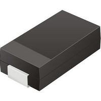
TV04A640JB-G
Description
TVS 400W 64V BIDIRECT SMA
Manufacturer
Comchip Technology
Specifications of TV04A640JB-G
Voltage - Reverse Standoff (typ)
64V
Voltage - Breakdown
71.1V
Power (watts)
400W
Polarization
Bidirectional
Mounting Type
Surface Mount
Package / Case
DO-214AC, SMA
Channels
1 Channel
Clamping Voltage
103 V
Operating Voltage
3.5 V
Breakdown Voltage
71.1 V
Peak Surge Current
40 A
Peak Pulse Power Dissipation
400 W
Lead Free Status / RoHS Status
Lead free / RoHS Compliant


19. AC Characteristics
Notes
1. Typical program and erase times assume the following conditions: 25°C, V
2. Under worst-case conditions of 90°C; V
3. Not 100% tested.
4. FAST_READ is not valid in parallel mode.
5. Only applicable as a constraint for WRSR command when SRWD is set to a ‘1’.
6. For “00” data pattern at 25°C.
September 8, 2009 S25FL128P_00_08
Symbol
t
t
HD:DAT
SU:DAT
F
F
t
t
t
t
t
t
t
t
t
WPS
WPH
CRT
t
t
CSS
CSH
t
t
t
t
t
t
t
RES
t
t
t
t
t
CFT
t
SCK
SCK
WH
DIS
t
WL
CS
HD
CD
HC
CH
t
HO
t
DP
t
LZ
HZ
PP
EP
SE
SE
BE
W
R
V
F
SCK Clock Frequency READ, RDID command
SCK Clock Frequency for:
FAST_READ, READ_ID, PP, SE, BE, DP, RES, WREN, WRDI, RDSR,
WRSR
Clock Rise Time (Slew Rate)
Clock Fall Time (Slew Rate)
SCK High Time
SCK Low Time
CS# High Time
CS# Setup Time
CS# HOLD Time
HOLD# Setup Time (relative to SCK)
HOLD# Non-Active Hold Time (relative to SCK)
HOLD# Non-Active Setup Time (relative to SCK)
HOLD# Hold Time (relative to SCK)
Output Valid
Output Hold Time
Data in Hold Time
Data in Setup Time
Input Rise Time
Input Fall Time
HOLD# to Output Low Z
HOLD# to Output High Z
Output Disable Time
Write Protect Setup Time (Notes 3, 5)
Write Protect Hold Time (Notes 3, 5)
Write Status Register Time
CS# High to Deep Power Down Mode
Release DP Mode
Page Programming Time
Page Programming Time (WP#/ACC = 9 V)
Sector Erase Time (64 KB)
Sector Erase Time (256 KB)
Bulk Erase Time
(Note 4)
(Note 3)
(Note 3)
CC
(Note 3)
= 2.7V; 100,000 cycles
(Note 3)
(Note 3)
D a t a
Parameter
Table 19.1 AC Characteristics
(Note 3)
S h e e t
(Note 3)
S25FL128P
CC
= 3.0 V; 10,000 cycles; checkerboard data pattern
0.25 (Parallel)
0.25 (Parallel)
50 (Parallel)
50 (Parallel)
20 (Parallel)
10 (Parallel)
10 (Parallel)
0.1 (Serial)
0.1 (Serial)
4.5 (Serial)
4.5 (Serial)
50 (Serial)
2 (Serial)
3 (Serial)
D.C.
D.C.
Min
100
20
3
3
3
3
3
3
0
0
1.02
128
1.2
0.5
2
(Notes)
(Note 1)
(Note 1)
(Note 1)
Typ
(Note 1)
(Note 6)
768
10 (Parallel)
20 (Parallel)
20 (Parallel)
20 (Parallel)
20 (Parallel)
2.4
104 (Serial)
12
6 (Parallel)
40 (Serial)
3
3
8 (Serial)
8 (Serial)
8 (Serial)
8 (Serial)
(Notes)
(Note 2)
(Note 2)
(Note 2)
Max
(Note 2)
100
(Note 2)
30
5
5
3
MHz
MHz
Unit
V/ns
V/ns
sec
sec
sec
sec
ms
ms
ns
ns
ns
ns
ns
ns
ns
ns
ns
ns
ns
ns
ns
ns
ns
ns
ns
ns
ns
ns
µs
µs
43
Related parts for TV04A640JB-G
Image
Part Number
Description
Manufacturer
Datasheet
Request
R

Part Number:
Description:
Manufacturer:
Comchip Technology Corporation
Datasheet:
Part Number:
Description:
Manufacturer:
Comchip Technology Corporation
Datasheet:
Part Number:
Description:
Manufacturer:
Comchip Technology Corporation
Datasheet:
Part Number:
Description:
Manufacturer:
Comchip Technology Corporation
Datasheet:
Part Number:
Description:
Manufacturer:
Comchip Technology Corporation
Datasheet:
Part Number:
Description:
Manufacturer:
Comchip Technology Corporation
Datasheet:
Part Number:
Description:
Manufacturer:
Comchip Technology Corporation
Datasheet:
Part Number:
Description:
Manufacturer:
Comchip Technology Corporation
Datasheet:
Part Number:
Description:
Manufacturer:
Comchip Technology Corporation
Datasheet:
Part Number:
Description:
Manufacturer:
Comchip Technology Corporation
Datasheet:
Part Number:
Description:
Manufacturer:
Comchip Technology Corporation
Datasheet:
Part Number:
Description:
Manufacturer:
Comchip Technology Corporation
Datasheet:
Part Number:
Description:
Manufacturer:
Comchip Technology Corporation
Datasheet:
Part Number:
Description:
Manufacturer:
Comchip Technology Corporation
Datasheet:
Part Number:
Description:
Manufacturer:
Comchip Technology Corporation
Datasheet: