TV04A180JB-G Comchip Technology, TV04A180JB-G Datasheet - Page 10
TV04A180JB-G
Manufacturer Part Number
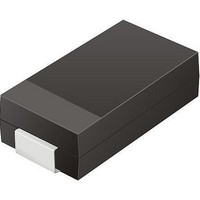
TV04A180JB-G
Description
TVS 400W 18V BIDIRECT SMA
Manufacturer
Comchip Technology
Specifications of TV04A180JB-G
Voltage - Reverse Standoff (typ)
18V
Voltage - Breakdown
20V
Power (watts)
400W
Polarization
Bidirectional
Mounting Type
Surface Mount
Package / Case
DO-214AC, SMA
Channels
1 Channel
Clamping Voltage
29.2 V
Operating Voltage
3.5 V
Breakdown Voltage
20 V
Peak Surge Current
40 A
Peak Pulse Power Dissipation
400 W
Lead Free Status / RoHS Status
Lead free / RoHS Compliant


DEVICE BUS OPERATIONS
This section describes the requirements and use of the
device bus operations, which are initiated through the
internal command register. The command register it-
self does not occupy any addressable memory loca-
tion. The register is composed of latches that store the
commands, along with the address and data informa-
tion needed to execute the command. The contents of
Legend:
L = Logic Low = V
Notes:
1. Addresses are A19:A0 in word mode (BYTE# = V
2. The sector protect and sector unprotect functions may also be implemented via programming equipment. See the “Sector
3. The 16 Kbyte boot sector is protected from erasure when WP# = V
4. In CMOS mode, WP# must be at V
Word/Byte Configuration
The BYTE# pin controls whether the device data I/O
pins DQ15–DQ0 operate in the byte or word configura-
tion. If the BYTE# pin is set at logic ‘1’, the device is in
word configuration, DQ15–DQ0 are active and control-
led by CE# and OE#.
If the BYTE# pin is set at logic ‘0’, the device is in byte
configuration, and only data I/O pins DQ0–DQ7 are ac-
tive and controlled by CE# and OE#. The data I/O pins
DQ8–DQ14 are tri-stated, and the DQ15 pin is used as
an input for the LSB (A-1) address function.
Requirements for Reading Array Data
To read array data from the outputs, the system must
drive the CE# and OE# pins to V
control and selects the device. OE# is the output control
8
Read
Write
Standby
Output Disable
Reset
Sector Protect
(Note 2)
Sector Unprotect
(Note 2)
Temporary Sector
Unprotect
Protection/Unprotection” section.
Operation
IL
, H = Logic High = V
V
0.5 V
CE#
CC
X
X
L
L
L
L
L
±
OE#
H
H
H
H
L
X
X
X
Table 1. Am29F160D Device Bus Operations
WE#
IL
H
X
H
X
X
L
L
L
CC
. CE# is the power
IH
±0.5 V or left floating.
, V
(Note 3)
(Note 4)
(Note 3)
ID
WP#
X
X
X
X
X
= 12.0 ± 0.5 V, X = Don’t Care, A
IH
D A T A S H E E T
RESET#
), A19:A-1 in byte mode (BYTE# = V
V
0.5 V
Am29F160D
V
V
V
CC
H
H
H
L
ID
ID
ID
±
Sector Address,
Sector Address,
the register serve as inputs to the internal state ma-
chine. The state machine outputs dictate the function of
the device. The appropriate device bus operations
table lists the inputs and control levels required, and the
resulting output. The following subsections describe
each of these operations in further detail.
A6 = H, A1 = H,
and gates array data to the output pins. WE# should re-
main at V
The internal state machine is set for reading array
data upon device power-up, or after a hardware reset.
This ensures that no spurious alteration of the mem-
ory content occurs during the power transition. No
command is necessary in this mode to obtain array
data. Standard microprocessor read cycles that as-
sert valid addresses on the device address inputs
produce valid data on the device data outputs. The
device remains enabled for read access until the
command register contents are altered.
See
tion. Refer to the AC Read Operations table for timing
specifications and to the Read Operations Timings di-
agram for the timing waveforms. I
A6 = L, A1 = H,
Addresses
(Note 1)
IL
A0 = L
A0 = L
.
A
A
A
Reading Array Data‚ on page 18
X
X
X
IN
IN
IN
IH
IN
.
= Address In, D
High-Z
High-Z
High-Z
DQ0–
D
DQ7
D
D
D
D
OUT
IN
IN
IN
IN
IL
Am29F160D_00_D10 April 23, 2010
).
BYTE#
High-Z
High-Z
High-Z
D
= V
D
D
IN
OUT
X
X
IN
IN
IH
= Data In, D
CC1
DQ8–DQ15
DQ8–DQ14 = High-Z,
for more informa-
in the DC Char-
DQ15 = A-1
OUT
BYTE#
High-Z
High-Z
High-Z
High-Z
= V
X
X
IL
= Data Out
Related parts for TV04A180JB-G
Image
Part Number
Description
Manufacturer
Datasheet
Request
R

Part Number:
Description:
Manufacturer:
Comchip Technology Corporation
Datasheet:
Part Number:
Description:
Manufacturer:
Comchip Technology Corporation
Datasheet:
Part Number:
Description:
Manufacturer:
Comchip Technology Corporation
Datasheet:
Part Number:
Description:
Manufacturer:
Comchip Technology Corporation
Datasheet:
Part Number:
Description:
Manufacturer:
Comchip Technology Corporation
Datasheet:
Part Number:
Description:
Manufacturer:
Comchip Technology Corporation
Datasheet:
Part Number:
Description:
Manufacturer:
Comchip Technology Corporation
Datasheet:
Part Number:
Description:
Manufacturer:
Comchip Technology Corporation
Datasheet:
Part Number:
Description:
Manufacturer:
Comchip Technology Corporation
Datasheet:
Part Number:
Description:
Manufacturer:
Comchip Technology Corporation
Datasheet:
Part Number:
Description:
Manufacturer:
Comchip Technology Corporation
Datasheet:
Part Number:
Description:
Manufacturer:
Comchip Technology Corporation
Datasheet:
Part Number:
Description:
Manufacturer:
Comchip Technology Corporation
Datasheet:
Part Number:
Description:
Manufacturer:
Comchip Technology Corporation
Datasheet:
Part Number:
Description:
Manufacturer:
Comchip Technology Corporation
Datasheet: