DAK-18 Power Integrations, DAK-18 Datasheet - Page 36
DAK-18
Manufacturer Part Number
DAK-18
Description
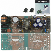
KIT DESIGN ACCELERATOR MODEM
Manufacturer
Power Integrations
Type
Design Accelerator Kit (DAK)r
Specifications of DAK-18
Contents
Power Supply, Samples, PCB, Software and Documentation
For Use With/related Products
TOP234P
Lead Free Status / RoHS Status
Not applicable / Not applicable
Other names
596-1002


Maximum Duty
Cycle Reduction
Onset Threshold
Current
Remote OFF
DRAIN Supply
Current
Remote ON Delay
Remote OFF
Setup Time
FREQUENCY INPUT
FREQUENCY Pin
Threshold Voltage
FREQUENCY Pin
Input Current
CIRCUIT PROTECTION
Self Protection
Current Limit
(See Note C)
36
MULTI-FUNCTION, LINSE-SENSE AND EXTERNAL CURRENT LIMIT INPUTS (cont.)
TOP242-250
Parameter
O
11/05
Symbol
I
I
L(DC)
t
I
t
D(RMT)
I
R(OFF)
M(DC)
R(ON)
LIMIT
V
I
F
F
or
TOP242 Y/R/F
TOP243 Y/R/F
TOP244 Y/R/F
TOP245 Y/R/F
TOP246 Y/R/F
TOP247 Y/R/F
Minimum Time Before Drain Turn-On
See Figure 71
V
TOP242 P/G
TOP243 P/G
TOP244 P/G
TOP245 P/G
TOP246 P/G
From Remote ON to Drain Turn-On
SOURCE = 0 V; T
DRAIN
T
T
T
T
T
T
T
T
T
T
J
J
J
J
J
J
J
J
J
J
(Unless Otherwise Specified)
to Disable Cycle, See Note B
= 25 °C
= 25 °C
= 25 °C
= 25 °C
= 25 °C
= 25 °C
= 25 °C
= 25 °C
= 25 °C
= 25 °C
= 150 V
Conditions
See Figure 53
See Note B
See Note B
T
J
V
= 25 °C
F
= V
L or M Pin Shorted
di/dt = 150 mA/µs
di/dt = 180 mA/µs
di/dt = 200 mA/µs
di/dt = 270 mA/µs
di/dt = 220 mA/µs
di/dt = 360 mA/µs
di/dt = 270 mA/µs
di/dt = 540 mA/µs
di/dt = 720 mA/µs
di/dt = 90 mA/µs
J
= -40 to 125 °C
to CONTROL
X, L or M Pin
C
Internal
Internal
Internal
Internal
Internal
Internal
Internal
Internal
Internal
Internal
Floating
0.418
0.697
0.837
0.930
1.256
1.674
1.256
3.348
2.511
Min
1.02
40
10
Typ
0.45
0.75
0.90
1.00
1.35
1.10
1.80
1.35
2.70
3.60
0.6
1.0
2.5
2.5
2.9
60
40
0.481
0.802
0.963
1.070
1.445
1.926
1.445
2.889
3.852
Max
1.18
100
1.0
1.6
75
Units
mA
µA
µA
µs
µs
V
A
Related parts for DAK-18
Image
Part Number
Description
Manufacturer
Datasheet
Request
R

Part Number:
Description:
KIT REF DES DPA 6.6W DC-DC CONV
Manufacturer:
Power Integrations
Datasheet:

Part Number:
Description:
KIT DESIGN ACCELERATOR POE CONV
Manufacturer:
Power Integrations
Datasheet:

Part Number:
Description:
DESIGN ACCELERATOR KIT XT SWITCH
Manufacturer:
Power Integrations
Datasheet:

Part Number:
Description:
DESIGN ACCELERATOR KIT LP SWITCH
Manufacturer:
Power Integrations
Datasheet:

Part Number:
Description:
KIT DESIGN ACC PEAKSWITCH FAMILY
Manufacturer:
Power Integrations
Datasheet:

Part Number:
Description:
KIT DESIGN ACCELERATOR ADAPTER
Manufacturer:
Power Integrations
Datasheet:

Part Number:
Description:
KIT DESIGN ACCELERATOR ADAPTER
Manufacturer:
Power Integrations
Datasheet:

Part Number:
Description:
KIT DESIGN ACCELERATOR DC-DC
Manufacturer:
Power Integrations
Datasheet:

Part Number:
Description:
KIT DESIGN ACCELERATOR DPA SW
Manufacturer:
Power Integrations
Datasheet:

Part Number:
Description:
KIT DESIGN ACCELERATOR AC/DC PS
Manufacturer:
Power Integrations
Datasheet: