DAK-18 Power Integrations, DAK-18 Datasheet - Page 12
DAK-18
Manufacturer Part Number
DAK-18
Description
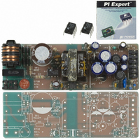
KIT DESIGN ACCELERATOR MODEM
Manufacturer
Power Integrations
Type
Design Accelerator Kit (DAK)r
Specifications of DAK-18
Contents
Power Supply, Samples, PCB, Software and Documentation
For Use With/related Products
TOP234P
Lead Free Status / RoHS Status
Not applicable / Not applicable
Other names
596-1002


be used as a remote ON/OFF and a synchronization input in
both modes. Please refer to Table 3 for possible combinations
of the functions with example circuits shown in Figure 30
through Figure 40. A description of specific functions in terms
of the MULTI-FUNCTION pin I/V characteristic is shown in
Figure 11. The horizontal axis represents MULTI-FUNCTION
pin current with positive polarity indicating currents flowing into
the pin. The meaning of the vertical axes varies with functions.
For those that control the ON/OFF states of the output such
as UV, OV and remote ON/OFF, the vertical axis represents
the enable/disable states of the output. UV triggers at I
Figure 11. MULTI-FUNCTION (P or G package), LINSE-SENSE, and EXTERNAL CURRENT LIMIT (Y, R or F package) Pin Characteristics.
12
TOP242-250
Pin Voltage
Duty Cycle
Note: This figure provides idealized functional characteristics with typical performance values. Please refer to the parametric
Switching
Maximum
MOSFET
Current
Output
O
11/05
Limit
table and typical performance characteristics sections of the data sheet for measured data.
-250
(Enabled)
(Disabled)
I
DC
LIMIT
MAX
-200
(Default)
X and L Pins (Y, R or F Package) and M Pin (P or G Package) Current (µA)
(78.5%)
-150
V
X Pin
BG
-100
-27 µA
-22 µA
-50
I
REM(N)
0
Disabled when supply
output goes out of
regulation
UV
I
50
UV
(+50 µA typical) and OV triggers at I
30 µA hysteresis). Between the UV and OV thresholds, the
output is enabled. For external current limit and line feed-
forward with DC
magnitude of the I
DC
(+60 µA typical) to 38% at I
limit is available only with negative MULTI-FUNCTION
pin current. Please see graphs in the Typical Performance
Characteristics section for the current limit programming
range and the selection of appropriate resistor value.
M Pin
100
MAX
V
BG
reduction lowers maximum duty cycle from 78% at I
+ V
150
TP
L Pin
200
MAX
LIMIT
reduction, the vertical axis represents the
I
OV
and DC
250
OV
300
MAX
(+225 µA). External current
. Line feed-forward with
OV
(+225 µA typical with
350
400
PI-2636-010802
I
I
I
I
M(DC)
Related parts for DAK-18
Image
Part Number
Description
Manufacturer
Datasheet
Request
R

Part Number:
Description:
KIT REF DES DPA 6.6W DC-DC CONV
Manufacturer:
Power Integrations
Datasheet:

Part Number:
Description:
KIT DESIGN ACCELERATOR POE CONV
Manufacturer:
Power Integrations
Datasheet:

Part Number:
Description:
DESIGN ACCELERATOR KIT XT SWITCH
Manufacturer:
Power Integrations
Datasheet:

Part Number:
Description:
DESIGN ACCELERATOR KIT LP SWITCH
Manufacturer:
Power Integrations
Datasheet:

Part Number:
Description:
KIT DESIGN ACC PEAKSWITCH FAMILY
Manufacturer:
Power Integrations
Datasheet:

Part Number:
Description:
KIT DESIGN ACCELERATOR ADAPTER
Manufacturer:
Power Integrations
Datasheet:

Part Number:
Description:
KIT DESIGN ACCELERATOR ADAPTER
Manufacturer:
Power Integrations
Datasheet:

Part Number:
Description:
KIT DESIGN ACCELERATOR DC-DC
Manufacturer:
Power Integrations
Datasheet:

Part Number:
Description:
KIT DESIGN ACCELERATOR DPA SW
Manufacturer:
Power Integrations
Datasheet:

Part Number:
Description:
KIT DESIGN ACCELERATOR AC/DC PS
Manufacturer:
Power Integrations
Datasheet: