TOOLSTICK931DC Silicon Laboratories Inc, TOOLSTICK931DC Datasheet - Page 9
TOOLSTICK931DC
Manufacturer Part Number
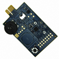
TOOLSTICK931DC
Description
DAUGHTER CARD TOOLSTCK C8051F931
Manufacturer
Silicon Laboratories Inc
Series
ToolStickr
Type
MCUr
Datasheet
1.TOOLSTICK931DC.pdf
(20 pages)
Specifications of TOOLSTICK931DC
Contents
Board
Accessory Type
Tool Stick Daughter Card
Peak Reflow Compatible (260 C)
No
Kit Contents
ToolStick C8051F931 Daughter Card, A76 Battery
Processor To Be Evaluated
C8051F931
Interface Type
USB
Operating Supply Voltage
2.7 V to 3.6 V
Development Tool Type
Hardware / Software - Dev Kit (Dev Tool)
Rohs Compliant
No
For Use With
336-1345 - TOOLSTICK BASE ADAPTER336-1182 - ADAPTER USB DEBUG FOR C8051FXXX
Lead Free Status / RoHS Status
Lead free / RoHS Compliant
For Use With/related Products
C8051F931
Lead Free Status / Rohs Status
Lead free / RoHS Compliant
Other names
336-1474


4. Press the S2 switch on the C8051F931 Daughter Card. This will place the system in Interactive mode. In this
5. Type the letter “P” into the Transfer Data text entry field and press the “Send Data” button to print the entire log to
6.3. Data Logger Modes and Indicator LEDs
The data logger has three modes of operation shown in Table 1:
The Logging Only mode is the lowest power mode and is the mode in which the data logger spends most of its
operating life. The primary goal of this mode is to prolong battery life and keep the data log up to date. The system
enters this mode when it is powered from the battery and the last reset was a power on reset or other reset not
caused by the reset pin. In this mode, the Yellow LED will blink when the S2 switch is pressed to indicate that the
system is in its lowest power mode.
The Logging + UART mode is entered when powered from the battery and a pin reset occurs. A pin reset is
generated on the C8051F931 Daughter Card when the ToolStick Terminal is connected. In this mode, the device
prints a log summary to the screen and blinks the Red LED when the S2 switch is pressed. This mode preserves
battery life, but it requires the MCU to stay in active mode while transmitting information over UART.
When the power source is set to ToolStick Power, the data logger will enter Interactive Mode. Since the MCU is
powered from the ToolStick Base Adapter, it runs at full speed without entering a low power mode. It constantly
monitors the potentiometer ratio, the capacitive touch sense switch oscillation period, and the current temperature.
Since the battery is disconnected when being powered from the ToolStick Base Adapter, the MCU cannot measure
the battery voltage. When S2 is pressed, the system toggles between displaying a log summary and interactive
content in addition to blinking both the Yellow and Red LEDs.
mode, the ToolStick Terminal is continuously refreshed with information about the number of seconds remaining
until the next Log entry, the current potentiometer ratio (%), the oscillation period of the Capacitive Touch Sense
Switch (SYSCLKs), and the current temperature (degrees C). Press the S2 switch again to return to the log
summary.
the ToolStick Terminal. Note: This step may take a few minutes depending on the log size.
Mode
Logging Only
Logging + UART
Interactive
ToolStick Base Adapter
Power Source
Battery
Battery
Table 1. Data Logger Modes
Rev. 0.1
Reset Source
POR or other
Don’t Care
/RST Pin
ToolStick-F931DC
Blinking Indicator LED(s)
Red and Yellow
Yellow Only
Red Only
9
Related parts for TOOLSTICK931DC
Image
Part Number
Description
Manufacturer
Datasheet
Request
R

Part Number:
Description:
KIT TOOL EVAL SYS IN A USB STICK
Manufacturer:
Silicon Laboratories Inc
Datasheet:

Part Number:
Description:
TOOLSTICK DEBUG ADAPTER
Manufacturer:
Silicon Laboratories Inc
Datasheet:

Part Number:
Description:
TOOLSTICK BASE ADAPTER
Manufacturer:
Silicon Laboratories Inc
Datasheet:

Part Number:
Description:
TOOLSTICK DAUGHTER CARD
Manufacturer:
Silicon Laboratories Inc
Datasheet:

Part Number:
Description:
TOOLSTICK DAUGHTER CARD
Manufacturer:
Silicon Laboratories Inc
Datasheet:

Part Number:
Description:
TOOLSTICK DAUGHTER CARD
Manufacturer:
Silicon Laboratories Inc
Datasheet:

Part Number:
Description:
TOOLSTICK DAUGHTER CARD
Manufacturer:
Silicon Laboratories Inc
Datasheet:

Part Number:
Description:
KIT STARTER TOOLSTICK
Manufacturer:
Silicon Laboratories Inc
Datasheet:

Part Number:
Description:
KIT UNIVERSITY TOOLSTICK STARTER
Manufacturer:
Silicon Laboratories Inc
Datasheet:

Part Number:
Description:
DAUGHTER CARD TOOLSTICK F330
Manufacturer:
Silicon Laboratories Inc
Datasheet:

Part Number:
Description:
CARD DAUGHTER UNIVRSTY TOOLSTICK
Manufacturer:
Silicon Laboratories Inc
Datasheet:

Part Number:
Description:
DAUGHTER CARD TOOLSTICK F582
Manufacturer:
Silicon Laboratories Inc
Datasheet:

Part Number:
Description:
DAUGHTER CARD TOOLSTICK F500
Manufacturer:
Silicon Laboratories Inc
Datasheet:

Part Number:
Description:
DAUGHTER CARD TOOLSTICK F540
Manufacturer:
Silicon Laboratories Inc
Datasheet:

Part Number:
Description:
DAUGHTER CARD TOOLSTICK F560
Manufacturer:
Silicon Laboratories Inc
Datasheet: