TOOLSTICK931DC Silicon Laboratories Inc, TOOLSTICK931DC Datasheet - Page 17
TOOLSTICK931DC
Manufacturer Part Number
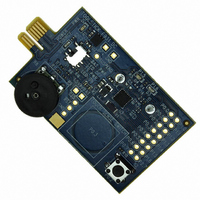
TOOLSTICK931DC
Description
DAUGHTER CARD TOOLSTCK C8051F931
Manufacturer
Silicon Laboratories Inc
Series
ToolStickr
Type
MCUr
Datasheet
1.TOOLSTICK931DC.pdf
(20 pages)
Specifications of TOOLSTICK931DC
Contents
Board
Accessory Type
Tool Stick Daughter Card
Peak Reflow Compatible (260 C)
No
Kit Contents
ToolStick C8051F931 Daughter Card, A76 Battery
Processor To Be Evaluated
C8051F931
Interface Type
USB
Operating Supply Voltage
2.7 V to 3.6 V
Development Tool Type
Hardware / Software - Dev Kit (Dev Tool)
Rohs Compliant
No
For Use With
336-1345 - TOOLSTICK BASE ADAPTER336-1182 - ADAPTER USB DEBUG FOR C8051FXXX
Lead Free Status / RoHS Status
Lead free / RoHS Compliant
For Use With/related Products
C8051F931
Lead Free Status / Rohs Status
Lead free / RoHS Compliant
Other names
336-1474


8. Additional Demo Examples
In addition to the F931DC_FeaturesDemo example firmware, the ToolStick download package also includes demo
projects named F931DC_CapTouchSense_Tune and F931DC_CapTouchSense_Switch. The instructions for
running these demos can be found at the top of the source file.
The
C:\SiLabs\MCU\ToolStick\F931DC\Firmware\ folder.
9. Using the C8051F931 Daughter Card as a Development Platform
The prototyping area on the ToolStick C8051F931 Daughter Card makes it easy to interface to external hardware.
All of the digital I/O pins are available so it possible to create a complete system.
9.1. C8051F931 Pin Connections
It is important to note that if external hardware is being added, some of the existing components on the board can
interfere with the signaling. The following is a list of port pins on the C8051F931 that are connected to other
components:
See the daughter card schematic in Section 11 for more information.
9.2. VREF Capacitor
On the C8051F931 devices, if VREF is generated using the High-Speed Internal Reference, no output capacitor is
required. If using the on-chip Precision Voltage Reference, it is highly recommended to place a capacitor on the
VREF output pin. On the ToolStick C8051F931 Daughter Card, there are pads on the board (C5) to populate a
0603 surface mount capacitor. There are also pads on the board (R14) to facilitate shorting P0.1 to the ground
plane for use as an analog ground reference (AGND). The firmware examples for the daughter card use the High-
Speed Internal Reference as VREF and the GND pin as a ground reference, so no external capacitor on P0.0 is
necessary for proper operation. Also, P0.1 may be used for general purpose I/O.
9.3. C2 Pin Sharing
On the C8051F931, the debug pins, C2CK, and C2D, are shared with the pins /RST and P2.7 respectively. The
daughter card includes the resistors necessary to enable pin sharing which allow the /RST and P2.7 pins to be
used normally while simultaneously debugging the device. See Application Note “AN124: Pin Sharing Techniques
for the C2 Interface” at
P0.2—This pin is connected to the P0.2 switch. The switch and R10 can be safely removed from the daughter
card if they are not needed.
P0.3—This pin is connected to a capacitive touch sense switch. The 0 Ω resistor R15 can be safely removed
from the daughter card if the capacitive touch sense switch is not needed.
P0.4, P0.5—These pins are connected directly to the ToolStick Base Adapter for UART communication.
P0.6—This pin is connected to the output of the potentiometer. The 0 Ω resistor R11 can be removed to
disconnect the potentiometer from the pin.
P1.0, P1.1—These pins are connected directly to the ToolStick Base Adapter’s GPIO pins. By default, these
GPIO pins on the Base Adapter are high-impedance pins so they will not affect any signaling. Configuring these
pins on the Base Adapter to output pin or handshaking pins could affect signaling.
P1.3—This pin is connected to the power source detect signal.
P1.4—This pin is connected to the potentiometer enable signal. This allows the potentiometer to be disabled by
software when not in use. The 0 Ω resistor R11 can be safely removed from the daughter card to disconnect the
potentiometer enable from the pin.
P1.5—This pin is connected to the cathode (-) of the red LED on the daughter card. The LED or R4 resistor can
be removed to disconnect the LED from the pin.
P1.6—This pin is connected to the cathode (-) of the yellow LED on the daughter card. The LED or R5 resistor
can be removed to disconnect the LED from the pin.
project
and
www.silabs.com
source
files
for more information regarding pin sharing.
for
these
Rev. 0.1
demos
can
ToolStick-F931DC
be
found
by
default
in
the
17
Related parts for TOOLSTICK931DC
Image
Part Number
Description
Manufacturer
Datasheet
Request
R

Part Number:
Description:
KIT TOOL EVAL SYS IN A USB STICK
Manufacturer:
Silicon Laboratories Inc
Datasheet:

Part Number:
Description:
TOOLSTICK DEBUG ADAPTER
Manufacturer:
Silicon Laboratories Inc
Datasheet:

Part Number:
Description:
TOOLSTICK BASE ADAPTER
Manufacturer:
Silicon Laboratories Inc
Datasheet:

Part Number:
Description:
TOOLSTICK DAUGHTER CARD
Manufacturer:
Silicon Laboratories Inc
Datasheet:

Part Number:
Description:
TOOLSTICK DAUGHTER CARD
Manufacturer:
Silicon Laboratories Inc
Datasheet:

Part Number:
Description:
TOOLSTICK DAUGHTER CARD
Manufacturer:
Silicon Laboratories Inc
Datasheet:

Part Number:
Description:
TOOLSTICK DAUGHTER CARD
Manufacturer:
Silicon Laboratories Inc
Datasheet:

Part Number:
Description:
KIT STARTER TOOLSTICK
Manufacturer:
Silicon Laboratories Inc
Datasheet:

Part Number:
Description:
KIT UNIVERSITY TOOLSTICK STARTER
Manufacturer:
Silicon Laboratories Inc
Datasheet:

Part Number:
Description:
DAUGHTER CARD TOOLSTICK F330
Manufacturer:
Silicon Laboratories Inc
Datasheet:

Part Number:
Description:
CARD DAUGHTER UNIVRSTY TOOLSTICK
Manufacturer:
Silicon Laboratories Inc
Datasheet:

Part Number:
Description:
DAUGHTER CARD TOOLSTICK F582
Manufacturer:
Silicon Laboratories Inc
Datasheet:

Part Number:
Description:
DAUGHTER CARD TOOLSTICK F500
Manufacturer:
Silicon Laboratories Inc
Datasheet:

Part Number:
Description:
DAUGHTER CARD TOOLSTICK F540
Manufacturer:
Silicon Laboratories Inc
Datasheet:

Part Number:
Description:
DAUGHTER CARD TOOLSTICK F560
Manufacturer:
Silicon Laboratories Inc
Datasheet: