C8051F326DK Silicon Laboratories Inc, C8051F326DK Datasheet
C8051F326DK
Specifications of C8051F326DK


Related parts for C8051F326DK

C8051F326DK Summary of contents
Page 1
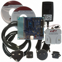
C8051F326 Kit Contents The C8051F326/7 Development Kit contains the following items: • C8051F326 Target Board • C8051Fxxx Development Kit Quick-Start Guide • Silicon Laboratories IDE and Product Information ...
Page 2
C8051F326/7-DK 3. Software Setup The included CD-ROM contains the Silicon Laboratories Integrated Development Environment (IDE), Keil software 8051 tools and additional documentation. Insert the CD-ROM into your PC’s CD-ROM drive. An installer will auto- matically launch, allowing you to install ...
Page 3
Creating a New Project → 1. Select Project New Project to open a new project and reset all configuration settings to default. → 2. Select File New File to open an editor window. Create your source file(s) and save ...
Page 4
C8051F326/7-DK 5. Example Source Code Example source code and register definition files are provided in the “SiLabs\MCU\Examples\C8051F326_7\” direc- tory during IDE installation. These files may be used as a template for code development. Example applications include a blinking LED example ...
Page 5
Target Board The C8051F326/7 Development Kit includes a target board with a C8051F326 device pre-installed for evaluation and preliminary software development. Numerous input/output (I/O) connections are provided to facilitate prototyp- ing using the target board. Refer to Figure 2 ...
Page 6
C8051F326/7-DK 6.1. System Clock Sources The C8051F326 device installed on the target board features a calibrated programmable internal oscillator which is enabled as the system clock source on reset. After reset, the internal oscillator operates at a frequency of 1.5 ...
Page 7
Expansion I/O Connector (J1) The 22-pin Expansion I/O connector J1 provides access to all signal pins of the C8051F326 device. Pins for +3 V, and digital ground are also available. A through-hole prototyping area is also provided. Each connection ...
Page 8
C8051F326/7-DK 6.6. Target Board DEBUG Interface (J4) The DEBUG connector (J4) provides access to the DEBUG (C2) pins of the C8051F326 used to connect the Serial Adapter or the USB Debug Adapter to the target board for in-circuit ...
Page 9
Schematics C8051F326/7-DK Rev. 0.2 9 ...
Page 10
C8051F326/7-DK 10 Rev. 0.2 ...
Page 11
OCUMENT HANGE IST Revision 0.1 to Revision 0.2 Removed EC2 Serial Adapter from Kit Contents. Removed Section 2. Hardware Setup using an EC2 Serial Adapter. See RS232 Serial Adapter (EC2) User's Guide. Removed Section 8. EC2 Serial ...
Page 12
... Should Buyer purchase or use Silicon Laboratories products for any such unintended or unauthorized ap- plication, Buyer shall indemnify and hold Silicon Laboratories harmless against all claims and damages. Silicon Laboratories and Silicon Labs are trademarks of Silicon Laboratories Inc. Other products or brandnames mentioned herein are trademarks or registered trademarks of their respective holders. ...