DM183026-2 Microchip Technology, DM183026-2 Datasheet - Page 30
DM183026-2
Manufacturer Part Number
DM183026-2
Description
KIT EVAL MTOUCH CAPACTIVIE
Manufacturer
Microchip Technology
Series
mTouch™r
Datasheet
1.DM183026-2.pdf
(54 pages)
Specifications of DM183026-2
Sensor Type
Touch, Capacitive
Sensing Range
8 & 12 Buttons/Keys, 2 Sliders
Interface
I²C
Voltage - Supply
5V, USB
Embedded
Yes
Utilized Ic / Part
PIC16F, PIC18F, PIC24F, PIC32MX
Interface Type
USB, I2C, UART
Operating Voltage
5 V
Data Bus Width
32 bit
Silicon Manufacturer
Microchip
Kit Application Type
Sensing - Touch / Proximity
Application Sub Type
Capacitive Touch
Kit Contents
8x Brds, Serial Anaylizer, USB Cable
For Use With/related Products
PIC16F, PIC24F, PIC18F, PIC32
Lead Free Status / RoHS Status
Lead free / RoHS Compliant
Sensitivity
-
Lead Free Status / Rohs Status
Lead free / RoHS Compliant
Available stocks
Company
Part Number
Manufacturer
Quantity
Price
Company:

Part Number:
DM183026-2
Manufacturer:
Microchip Technology
Quantity:
135
Company:
Part Number:
DM183026-2
Manufacturer:
MICROCHIP
Quantity:
12 000


mTouch™ Advanced Capacitive Evaluation Kits User’s Guide
FIGURE 4-4:
DS41385C-page 30
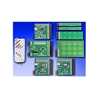
PLUG-IN BOARDS
Direct Key Slider
Programming
Serial Header
Plug-in Board
Plug-in
Slider Plug-in
Slider Plug-in
I
2
Matrix Key
7-Channel
2-Channel
4-Channel
8-Channel
C PICkit™
Header
Board
Board
J2
J1
Board
For users interested in using the evaluation board as an experimental platform, the
microcontroller can be reprogrammed using the ICSP connector. A 6-pin header is
provided for connecting the evaluation board to any MPLAB ICD 2 compatible
programmer. Since the ICD interface (PGD and PGC) shares some input channels of
the connector, J4/J3 (channel 6 and 7), necessary care should be taken when the
debugger is enabled.
The firmware in the evaluation board will have the default plug-in board channel
configurations, which is explained in the Readme.txt file. The user can reconfigure
the channels based on his application by referring to the Readme.txt file.
4.1.4
The PIC24H CVD Evaluation Board (see Figure 4-4) is based on the same layout as
the PIC24F CTMU and PIC32MX CVD evaluation boards and has similar functional
characteristics as the PIC16F CSM evaluation board (I
This board do not use USB and a PICkit to power the board. The USB has a 3.3V
regulator to regulate the USB power and the PICkit tools have their own regulator
straight to the device VDD; so, choose one or the other.
PIC24H CVD EVALUATION BOARD APPLICATION-SIDE BLOCK DIAGRAM
ICSP™
PIC24H CVD Evaluation Board
I
2
C™
J3
J4
AN0-AN15
ICSPDAT
ICSPCLK
MCLR
V
V
DD
SS
PIC24H CVD EVALUATION BOARD
PIC24HJ128GP506
GPIO
V
Vss
DD
J5
2
C interface with host).
© 2010 Microchip Technology Inc.
16 LEDs (D1-D16)
Sensor Boards
USB mini-B
Receptacle
Related parts for DM183026-2
Image
Part Number
Description
Manufacturer
Datasheet
Request
R

Part Number:
Description:
Manufacturer:
Microchip Technology Inc.
Datasheet:
Part Number:
Description:
Manufacturer:
Microchip Technology Inc.
Datasheet:
Part Number:
Description:
Manufacturer:
Microchip Technology Inc.
Datasheet:
Part Number:
Description:
Manufacturer:
Microchip Technology Inc.
Datasheet:
Part Number:
Description:
Manufacturer:
Microchip Technology Inc.
Datasheet:
Part Number:
Description:
Manufacturer:
Microchip Technology Inc.
Datasheet:
Part Number:
Description:
Manufacturer:
Microchip Technology Inc.
Datasheet:
Part Number:
Description:
Manufacturer:
Microchip Technology Inc.
Datasheet: