DM183026-2 Microchip Technology, DM183026-2 Datasheet
DM183026-2
Specifications of DM183026-2
Available stocks


Related parts for DM183026-2

DM183026-2 Summary of contents
Page 1
... Advanced Capacitive © 2010 Microchip Technology Inc. Evaluation Kits User’s Guide DS41385C ...
Page 2
... PICtail, REAL ICE, rfLAB, Select Mode, Total Endurance, TSHARC, UniWinDriver, WiperLock and ZENA are trademarks of Microchip Technology Incorporated in the U.S.A. and other countries. SQTP is a service mark of Microchip Technology Incorporated in the U.S.A. All other trademarks mentioned herein are property of their respective companies. ...
Page 3
... Board Components ...................................................................................... 32 4.3 Interfacing to the Evaluation Boards ............................................................ 38 Chapter 5. Troubleshooting 5.1 Common Issues ........................................................................................... 41 Appendix A. Evaluation Board Schematics Appendix B. mTouch™ PIC16F CSM State Diagrams Index ............................................................................................................................. 53 Worldwide Sales and Service .................................................................................... 54 © 2009 Microchip Technology Inc. UATION KITS USER’S GUIDE Table of Contents DS41385C-page 3 ...
Page 4
... Advanced Capacitive Evaluation Kits User’s Guide DS41385C-page 4 © 2009 Microchip Technology Inc. ...
Page 5
... Chapter 5. Troubleshooting – This chapter provides troubleshooting tips for commonly encountered issues. • Appendix A. “Evaluation Board Schematics” – This appendix provides © 2010 Microchip Technology Inc. mTouch™ ADVANCED CAPACITIVE EVALUATION KITS USER’S GUIDE Preface NOTICE TO CUSTOMERS ® ...
Page 6
... Optional arguments mcc18 [options] file [options] Choice of mutually exclusive errorlevel {0|1} arguments selection Replaces repeated text var_name [, var_name...] Represents code supplied by void main (void) user { ... } © 2010 Microchip Technology Inc. Examples ® IDE User’s Guide ...
Page 7
... MPLAB Assembler Linker and Utilities for PIC24 MCUs and dsPIC DSCs User’s Guide (DS51317) This document details Microchip Technology’s language tools for dsPIC based on GNU technology. The language tools discussed are: • MPLAB Assembler PIC24 MCUs and dsPIC • MPLAB Linker PIC24 MCUs and dsPIC • ...
Page 8
... MPLAB Assembler Linker and Utilities for PIC32 MCUs User’s Guide (DS51833) This document details Microchip Technology’s language tools for PIC32 MCU devices based on GNU technology. The language tools discussed are: • MPLAB Assembler PIC32 MCUs • MPLAB Linker PIC32 MCUs • ...
Page 9
... Microchip mTouch™ Sensing Solutions Webinars Currently, there are three online Webinars available for mTouch Sensing Solutions: • Introduction to mTouch™ Capacitive Touch Sensing • Capacitive mTouch™ Sensing Solutions: Design Guidelines • Overview of Charge Time Measurement Unit (CTMU) © 2010 Microchip Technology Inc. Preface DS41385C-page 9 ...
Page 10
... Programmers – The latest information on Microchip programmers. These include the MPLAB PM3 and PRO MATE Plus and PICkit™ and 3 development programmers. DS41385C-page 10 ® II device programmers and the PICSTART © 2010 Microchip Technology Inc. ® ® ...
Page 11
... Modified the Kit Contents list • Added the PIC32 CVD Touch Evaluation Board • Added block diagrams for the PIC24H CVD and PIC32 CVD Evaluation Boards • Updated PIC16F CSM/CVD Evaluation Board schematic and layout © 2010 Microchip Technology Inc. Preface DS41385C-page 11 ...
Page 12
... Advanced Capacitive Evaluation Kits User’s Guide NOTES: DS41385C-page 12 © 2010 Microchip Technology Inc. ...
Page 13
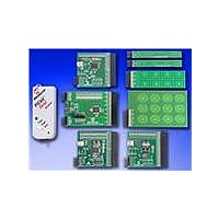
... Evaluation Kit. Depending on the kit purchased four individual evaluation boards are provided. These evaluation boards are intended to introduce and demonstrate the possibilities for capacitive touch sense applications on the PIC16F, PIC18F, PIC24F, (DM183026-2 kit), PIC24H (AC243026 kit) and PIC32MX microcontroller platforms. Note: This Evaluation Kit is intended as a functional evaluation of Microchip’s mTouch Capacitive Sensing Solutions ...
Page 14
... This allows the board to also be used as a test platform for capacitive touch sense applications. 1.1.1 mTouch Advanced Capacitive Evaluation Kit Contents The mTouch Advanced Capacitive Evaluation Kit (DM183026-2) contains the following items: • PIC16F CSM Evaluation Board • PIC18F CVD/CSM Evaluation Board • ...
Page 15
... PC-compatible system with a CD-ROM drive • One available USB port on the powered USB hub ® • Microsoft Windows © 2010 Microchip Technology Inc. PIC24H CAPACITIVE TOUCH EVALUATION KIT CONTENTS ® XP SP2, Windows 7, or Windows Vista (32-bit) DS41385C-page 15 ...
Page 16
... If you do not see these messages and the evaluation board does not work, try unplugging and reconnecting the USB cable. If this does not work, see Chapter 5. “Troubleshooting”. DS41385C-page 16 © 2010 Microchip Technology Inc. ...
Page 17
... The demonstration code supplied takes most of the typical environmental factors into consideration. The demonstration application is very flexible in the sense that it can be modified by the user. © 2010 Microchip Technology Inc. mTouch™ ADVANCED CAPACITIVE EVALUATION KITS USER’S GUIDE ...
Page 18
... LEDs, D9 through D15, will be lit. Here, one LED will be lit for every press key on the plug-in board (see Figure 2-1). FIGURE 2-1: DS41385C-page 18 DEFAULT PLUG-IN CHANNELS FOR 8-KEY PLUG-IN BOARD © 2010 Microchip Technology Inc. ...
Page 19
... Readme.txt file, which is distributed in each demonstration. 2: Plugging a sensor board in while an evaluation board is running, may require resetting the touch algorithm, most easily done by cycling power. © 2010 Microchip Technology Inc. Demonstration Application DEFAULT PLUG-IN CHANNELS FOR 4-CHANNEL SLIDER PLUG-IN BOARD DS41385C-page 19 ...
Page 20
... Advanced Capacitive Evaluation Kits User’s Guide FIGURE 2-3: FIGURE 2-4: DS41385C-page 20 PLUG IN THE SENSORS BEFORE POWERING BOARD PLUG IN POWER AFTER SYSTEM IS CONFIGURED © 2010 Microchip Technology Inc. ...
Page 21
... This section describes the MPLAB IDE integrated mTouch Diagnostic Tool GUI features. The following firmware items from the mTouch Advanced Capacitive Evaluation Kit (DM183026) were tested using this GUI: • PIC16F CSM Evaluation Board • PIC18F CTMU Evaluation Board • PIC24F CTMU Evaluation Board • ...
Page 22
... Settings and Touch Status. The Touch Status tab enable visualization of the pressed button with the specific Board shape as selected in the Settings tab. Click the Settings button in the Settings tab to display the window, as shown in Figure 3-2. DS41385C-page 22 THE mTOUCH™ SENSING SOLUTION AT START-UP ® (MPLAB IDE) © 2010 Microchip Technology Inc. ...
Page 23
... I2C (Slave Address) and UART (Port and Baud Rate). Choose one option only by selecting the appropriate radio button. • PICkit Serial Setting: This contains the options - Provides Power and Supplied Voltage. © 2010 Microchip Technology Inc. THE mTOUCH™ DIAGNOSTIC TOOL - BOARD SETTINGS ® (MPLAB ...
Page 24
... The Logging tab, as shown in Figure 3-4, includes the settings typical for logging data such as data contained by the log, destination file and data delimiter. FIGURE 3-4: DS41385C-page 24 THE mTOUCH™ DIAGNOSTIC TOOL - COMMUNICATION ® SETTINGS (MPLAB IDE) THE MTOUCH™ DIAGNOSTIC TOOL - LOGGING SETTINGS ® (MPLAB IDE) © 2010 Microchip Technology Inc. ...
Page 25
... Raw data represents working data values divided by 16. The Display Data settings can be applied to the sensor selected or to all sensors. © 2010 Microchip Technology Inc. THE mTOUCH™ DIAGNOSTIC TOOL - DISPLAY DATA ® ...
Page 26
... Settings window, if not, the error "Trip Value Can't be Set!, Change Settings to GUI Trip" is displayed. DS41385C-page 26 THE mTOUCH™ DIAGNOSTIC TOOL - ZOOM SETTINGS ® (MPLAB IDE) THE mTOUCH™ DIAGNOSTIC TOOL - SENSOR SETTINGS ® (MPLAB IDE) © 2010 Microchip Technology Inc. ...
Page 27
... Matrix Key Plug-in Board 2-Channel Slider Plug-in Board 4-Channel Slider Plug-in Board 8-Channel Direct Key Slider Plug-in Board PLUG-IN BOARDS © 2010 Microchip Technology Inc. mTouch™ ADVANCED CAPACITIVE EVALUATION KITS USER’S GUIDE 2 C™ PIC16F1937 ICSPDAT ICSPCLK MCLR GPIO ...
Page 28
... J3 J5 D+/D- PIC18F CTMU EVALUATION BOARD by Q1, an MCP1702 BUS 16 LEDs (D1-D16) D8-D15 Direct Key Plug-in Board LEDs D1-D12 Matrix Key Plug-in Board LEDs D1-D16 2-Channel and 4-Channel Slider Plug-in LEDs USB mini-B Receptacle Q1 Power Supply (3.3V) © 2010 Microchip Technology Inc. ...
Page 29
... USB receptacle for application power as a bus-powered device. Microcontroller and LED power are provided from the V voltage regulator. Provisions on the board allow for users to add components and create an externally powered application. © 2010 Microchip Technology Inc. Evaluation Board Hardware PIC24FJ128GB106 PGC/EMUC ...
Page 30
... Slider Plug-in Board 8-Channel Direct Key Slider Plug-in Board PLUG-IN BOARDS DS41385C-page 30 C™ PIC24HJ128GP506 ICSPDAT ICSPCLK MCLR GPIO J4 AN0-AN15 Vss PIC24H CVD EVALUATION BOARD 2 C interface with host). 16 LEDs (D1-D16) Sensor Boards J5 USB mini-B Receptacle © 2010 Microchip Technology Inc. ...
Page 31
... Matrix Key Plug-in Board 2-Channel Slider Plug-in Board 4-Channel Slider Plug-in Board 8-Channel Direct Key Plug-in Board PLUG-IN BOARDS © 2010 Microchip Technology Inc. Evaluation Board Hardware PIC32MX795F512H PGC/EMUC PGD/EMUD MCLR RD0-RD7 RE0:RE7 J4 AN0:AN15 J3 J5 D+/D- PIC32MX CVD EVALUATION BOARD ...
Page 32
... PIC16F1937 Microcontroller (U1) for PIC16F CSM Board 2 USB mini-B Receptacle (J5) 3 ICSP™ Programming Header (J1) 4 Power Supply (U2) to provide the V 5 Plug-in Sensor LEDs (D1-D16) 6 Plug-in Interface Connector (J4/J3) 7 PICkit serial analyzer connector DS41385C-page Component to the Evaluation Board DD © 2010 Microchip Technology Inc. 6 ...
Page 33
... CTMU, PIC24F CTMU, and PIC32MX CVD evaluation boards. There is one evaluation board and four plug-in daughter boards. The four plug-in daughter boards are identified as direct keys, matrix keys, 2-channel slider and 4-channel slider. © 2010 Microchip Technology Inc. Evaluation Board Hardware 2 C using the PICkit Serial Analyzer ...
Page 34
... The microcontroller features 64 Kbytes of Flash program memory and 16 Kbytes RAM, allowing sufficient space for the development of more complex touch sense applications. DS41385C-page 34 2 R16 R15 J1 C13 Component to the Evaluation Board DD R14 R13 R12 R11 R10 © 2010 Microchip Technology Inc. ...
Page 35
... Plug-in Interface Connector (J4/J3): This is a 48-pin connector, which is used to interface the different plug-in boards to the microcontroller. This connector is interfaced to 16 analog channels of the microcontroller and the remaining pins are connected to ground of the evaluation board. © 2010 Microchip Technology Inc. Evaluation Board Hardware required by the evaluation board. ® ...
Page 36
... PIC24HJ128GP506A Microcontroller (U1) for PIC24H CVD Board 2 USB mini-B Receptacle (J5) 3 ICSP™ Programming Header (J1) 4 Power Supply (Q1) to provide the V 5 Plug-in Sensor LEDs (D1-D16) 6 Plug-in Interface Connector (J4/J3) 7 PICkit serial analyzer connector DS41385C-page Component to the Evaluation Board © 2010 Microchip Technology Inc. ...
Page 37
... Plug-in Interface Connector (J4/J3): This is a 48-pin connector, which is used to interface the different plug-in boards to the microcontroller. This connector is interfaced to 16 analog channels of the microcontroller and the remaining pins are connected to ground of the evaluation board. © 2010 Microchip Technology Inc. Evaluation Board Hardware 2 C using the PICkit Serial Analyzer. ...
Page 38
... USB communication. DS41385C-page 38 CAUTION ® MPLAB ICSP™ REAL ICE™ J1 In-circuit Connector Emulator Evaluation Board SIP PICkit Serial J6 Analyzer Connector A to mini-B USB Cable ICD 3 USB Cable Workstation USB Cable (1) © 2010 Microchip Technology Inc. ...
Page 39
... PGC) shares two of the input channels of the connector, J4/J3 (channel 6 and channel 7), the operation might fail if any of the plug-in boards is connected to these 2 channels when the Debugger mode is enabled in the MPLAB © 2010 Microchip Technology Inc. Evaluation Board Hardware ® ICSP™ ...
Page 40
... Advanced Capacitive Evaluation Kits User’s Guide NOTES: DS41385C-page 40 © 2010 Microchip Technology Inc. ...
Page 41
... The board’s edge connector will add some additional parasitic capacitance to the system. 5. Touching the solder connections can create a very strong coupling to the sensor and trigger buttons. © 2010 Microchip Technology Inc. mTouch™ ADVANCED CAPACITIVE EVALUATION KITS USER’S GUIDE , + present on the USB connection ...
Page 42
... Advanced Capacitive Evaluation Kits User’s Guide NOTES: DS41385C-page 42 © 2010 Microchip Technology Inc. ...
Page 43
... Figure A-3: “mTouch™ – PIC24F CTMU Evaluation Board Schematic” • Figure A-4: “mTouch™ – PIC24H CVD Evaluation Board Schematic” • Figure A-5: “mTouch™ – PIC32MX CVD Evaluation Board Schematic” © 2010 Microchip Technology Inc. mTouch™ ADVANCED CAPACITIVE EVALUATION KITS USER’S GUIDE ...
Page 44
... Advanced Capacitive Evaluation Kits User’s Guide FIGURE A-1: mTouch™ – PIC16F CSM/CVD EVALUATION BOARD SCHEMATIC DS41385C-page 44 © 2010 Microchip Technology Inc. ...
Page 45
... BUS 0.1 4.7uF 5 6 Note: The Channels13,14 and 15 are not used, and are grounded in the PIC18F CTMU Evaluation Board. © 2010 Microchip Technology Inc. Evaluation Board Schematics RD5 RD6 RD7 D10 D11 D9 D14 D15 D13 C3 0.1 1 RC7R /DT RC7 X 2 N/C ...
Page 46
... Advanced Capacitive Evaluation Kits User’s Guide FIGURE A-3: mTouch™ – PIC24F CTMU EVALUATION BOARD SCHEMATIC DS41385C-page 46 © 2010 Microchip Technology Inc. ...
Page 47
... PIC24H CVD EVALUATION BOARD SCHEMATIC RD1 RD2 RD3 RD4 RD5 RD6 RD7 VDD RF0 RF1 RE0 RE1 RE2 RE3 RE4 © 2010 Microchip Technology Inc. Evaluation Board Schematics RF5 RF4 BTN_15 BTN_14 BTN_13 BTN_12 BTN_11 BTN_10 BTN_9 BTN_8 PGD PGC DS41385C-page 47 ...
Page 48
... PIC32MX CVD EVALUATION BOARD SCHEMATIC RD1 RD2 RD3 RD4 RD5 RD6 RD7 VDD RF0 RF1 RE0 RE1 RE2 RE3 RE4 DS41385C-page 48 RF5 RF4 BTN_15 BTN_14 BTN_13 BTN_12 BTN_11 BTN_10 BTN_9 BTN_8 PGD PGC © 2010 Microchip Technology Inc. ...
Page 49
... FIGURE B-1: mTouch™ – PIC16F CSM STATE DIAGRAMS Start – main.c InitializeSystem() No CalculateButton? Yes CapSenseStateMachine() ButtonDecode() © 2010 Microchip Technology Inc. mTouch™ ADVANCED CAPACITIVE EVALUATION KITS USER’S GUIDE Start – isr() 2 Service I Interrupt for mTouch™ GUI Overflow ...
Page 50
... FIGURE B-1: mTouch™ – PIC16F CSM STATE DIAGRAMS (CONTINUED) Yes InitializeSystem() Yes InitializeSystem() DS41385C-page 50 Start – CapSenseStateMachine() Correct, Scale and Cap CurrentSample Is ReleaseAverage[ButtonIndex] outside of ReleaseAverageGuardBand SupplyVoltage outside of VoltageGuardBand? No Calculate PercentReleased State Machine Design (next page) Return © 2010 Microchip Technology Inc. ...
Page 51
... ReleaseCount ReleaseDebounce: Start Debounce counter PercentReleased < PercentReleased > OffThreshold OffThreshold PressedTime < ButtonTimeout Pressed: Start ButtonTimout counter © 2010 Microchip Technology Inc. SetSampleTime: StartUpDelay MeasureSamplePeriod complete for each Button and once for each Button in average in ReleasedAverage 1/2 StartUpDelay is timing StartUpDelay complete Debounce Counter > ReleaseCount ...
Page 52
... PIC16F CSM STATE DIAGRAMS (CONTINUED) No Turn LED1 Off No Turn LED2 Off No Turn LED16 Off DS41385C-page 52 Start – ButtonDecode() Yes ButtonState[Button0] > Turn LED1 On Released Yes ButtonState[Button1] > Turn LED2 On Released ETC... Yes ButtonState[ButtonF] > Turn LED16 On Released Return © 2010 Microchip Technology Inc. ...
Page 53
... E Evaluation Board CTMU and CVD Component Layout (Top Side)34 H Host Computer Requirements.................................. 15 I Initial Board Setup.................................................... 16 Internet Address....................................................... 10 © 2010 Microchip Technology Inc. mTouch™ ADVANCED CAPACITIVE EVALUATION KITS USER’S GUIDE Index K Kit Contents.............................................................. 14 M Matrix Key Plug-in .................................................... 19 Microchip Internet Web Site ..................................... 10 ...
Page 54
... Philippines - Manila Tel: 63-2-634-9065 Fax: 63-2-634-9069 Singapore Tel: 65-6334-8870 Fax: 65-6334-8850 Taiwan - Hsin Chu Tel: 886-3-6578-300 Fax: 886-3-6578-370 Taiwan - Kaohsiung Tel: 886-7-536-4818 Fax: 886-7-536-4803 Taiwan - Taipei Tel: 886-2-2500-6610 Fax: 886-2-2508-0102 Thailand - Bangkok Tel: 66-2-694-1351 Fax: 66-2-694-1350 © 2010 Microchip Technology Inc. 01/05/10 ...