AS5134 DB austriamicrosystems, AS5134 DB Datasheet - Page 19
AS5134 DB
Manufacturer Part Number
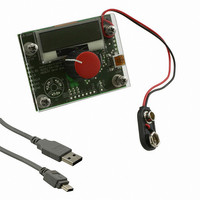
AS5134 DB
Description
BOARD DEMO AS5134
Manufacturer
austriamicrosystems
Specifications of AS5134 DB
Sensor Type
Magnetic, Rotary Position
Sensing Range
360°
Interface
USB
Voltage - Supply
5V USB or 9V
Embedded
Yes, MCU, 8-Bit
Utilized Ic / Part
AS5134
Lead Free Status / RoHS Status
Lead free by exemption / RoHS compliant by exemption
Sensitivity
-


AS5134
Data Sheet - D e t a i l e d D e s c r i p t i o n
Table 9. Commands of the SSI in Normal Mode
SM_RES: State machine reset of the digital part of the device (soft reset).
EN PROG: Enables the access to the OTP register in Extended Mode.
WRITE CONFIG: LP HI activates the sleep mode of the AS5134. The power consumption is significantly reduced. LP LO returns to normal
operation mode. During sleep mode, the lock_adc bit in command 0 is LO.
RD_MT Counter: Command for read out of multi turn register.
otp_ok: Bit shows correct readout of the OTP register after startup. The bit is valid till the next OTP access.
RD_ANGLE: Command for read out of angle value and AGC value (agc). “Lock” indicates a locked ADC.
tst: Test bits for internal testing (must be left unchanged).
Hyst (11:10): Digital Hysteresis can be set via the digital interface 0,1,2 (default) 3 LSB
The hysteresis can be changed over the interface. An activation of the SM_RES bit is required. This can be performed in two steps -
SET MT COUNTER: Command for setting the Multi Turn Counter to a defined value.
LP: Default "0"; "1" for using the low power function.
lock_adc: Indicates that the tracking adc is in a locked status. For a valid angle (the magnetic field has to be in a certain range, which is
indicated by the agc value) or a missing magnet the lock_adc is set.
Table 10. Commands of the SSI in Extended Mode
www.austriamicrosystems.com/AS5134
31
25 PROG_
16
#
#
4
0
1. use WRITE CONFIG 1 command and write the selected hysteresis and SM_RES = ‘1’ into the device.
2. use again WRITE CONFIG 1 command and release SM_RES = ‘0’ with the same hysteresis setting.
WRITE
RD_ANGLE
cmd
OTP
OTP
COUNTER
EN PROG
number of bits
RD MT
cmd
0
0
1
1
11001 xt write
11111
bin
10000
00100
00000
bin
xt write
mode
Hyst
mode
write
read
read
..60
61
tst
tst
2
lock_
adc
..42 41 40
15
18
59
ID
ID
1
tst tst
tst tst
1
0
1
0
1
14
0
Digital interface at extended mode
1
Digital interface at normal mode
13
0
multi-turn-counter <8:0>
..36
39
tst
tst
Factory Settings
4
agc <5:0>
12
0
..32 31
35
tst
tst
4
Revision 1.13
11
1
tst
tst
1
10
..27
1
30
tst
tst
4
9
0
..25
26
tst
tst
2
8
0
..22
24
tst
tst
3
2 LSB (default value)
7
1
lock_
lock_
otp
otp
21
(*)
(*)
1
otp_
Function
ok
6
0
..17 16
add
add
20
r_
r_
1
3
0
4
5
1
angle <8:0>
r_b
r_b
1
it
it
Customer Settings
4
0
itivity
itivity
sens
sens
..14
15
2
3
1
..12
abi
abi
13
2
2
1
uvw
uvw
..9
11
3
1
1
angle
angle
zero
zero
19 - 40
8..0
9
0
0
Related parts for AS5134 DB
Image
Part Number
Description
Manufacturer
Datasheet
Request
R

Part Number:
Description:
IC ENCODER PROG 20-SSOP
Manufacturer:
austriamicrosystems
Datasheet:

Part Number:
Description:
BOARD PROGRAM AS5134
Manufacturer:
austriamicrosystems
Datasheet:

Part Number:
Description:
ENCODER, MAGNETIC, ROTARY, 8BIT, 20SSOP
Manufacturer:
austriamicrosystems
Datasheet:
Part Number:
Description:
360?programmable High Speed Bldc Magnetic Rotary Encoder
Manufacturer:
austriamicrosystems
Datasheet:
Part Number:
Description:
IC SWITCH QUAD SPST 14-TSSOP
Manufacturer:
austriamicrosystems
Datasheet:
Part Number:
Description:
IC SWITCH QUAD SPST 14-TSSOP
Manufacturer:
austriamicrosystems
Datasheet:
Part Number:
Description:
IC AMP AUDIO MONO 1.8W 10-MSOP
Manufacturer:
austriamicrosystems
Datasheet:
Part Number:
Description:
IC AMP AUDIO MONO 1.8W 10-MSOP
Manufacturer:
austriamicrosystems
Datasheet:
Part Number:
Description:
IC AMP AUDIO MONO 1.8W 10-MSOP
Manufacturer:
austriamicrosystems
Datasheet:
Part Number:
Description:
IC AMP AUD 1.8W 3DB GAIN 10-MSOP
Manufacturer:
austriamicrosystems
Datasheet:
Part Number:
Description:
IC DRIVER LED 8-DIGIT 24-SOIC
Manufacturer:
austriamicrosystems
Datasheet:
Part Number:
Description:
IC DRIVER LED 8-DIGIT 24-SOIC
Manufacturer:
austriamicrosystems
Datasheet:
Part Number:
Description:
IC, LINE/SPEAKER PHONE CIRCUIT, SOIC-28
Manufacturer:
austriamicrosystems
Datasheet:
Part Number:
Description:
IC MULTI-STANDARD CMOS TELEPHONE SOIC-28
Manufacturer:
austriamicrosystems
Datasheet:
Part Number:
Description:
IC MULTI-STANDARD CMOS TELEPHONE SOIC-28
Manufacturer:
austriamicrosystems
Datasheet: