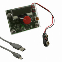
AS5134 DB austriamicrosystems, AS5134 DB Datasheet - Page 17

AS5134 DB
Manufacturer Part Number
AS5134 DB
Description
BOARD DEMO AS5134
Manufacturer
austriamicrosystems
Specifications of AS5134 DB
Sensor Type
Magnetic, Rotary Position
Sensing Range
360°
Interface
USB
Voltage - Supply
5V USB or 9V
Embedded
Yes, MCU, 8-Bit
Utilized Ic / Part
AS5134
Lead Free Status / RoHS Status
Lead free by exemption / RoHS compliant by exemption
Sensitivity
-
AS5134
Data Sheet - D e t a i l e d D e s c r i p t i o n
Waveform – Digital Interface at Three Wire Daisy Chain Mode
Note: Defined if the Pin C2 is set to LO at all devices
Figure 12. 3-Wire Daisy Chain Mode
www.austriamicrosystems.com/AS5134
bidirectional data input output
Daisy Chain Port
DX(1) = CS(2)
DX(2) = CS(3)
CS_INT(1)
CS_INT(2)
CS_INT(3)
DCLK
CS(1)
Port
C4 C3 C2 C1 C0 D15 D14 D13
CMD(1)
DIO
CS
CLK
Symbol
DIO
Dx
DIO
CLK
CS
Data(1)
LO
C2
Command and data information over one single line. The first bit of the command
defines a read or write access.
This port enables the daisy chain configuration of several devices.
Three wire mode: Indicates the end of an interface cycle. Dx can be used as the
chip select signal for the next device in the chain.
Two wire mode: Will be set with the first falling edge of DCLK and hence, indicates
a running clock; it will be cleared at the end of the command sequence or after a
timeout phase. Dx can be used as a chip select signal in the two wire mode.
DX
D0 C4
DX(1)
Revision 1.13
CMD(2)
DIO
CLK
CS
C0 D15 D14
LO
C2
DX
Data(2)
DX(2)
D0 C4
DIO
CLK
CS
Function
CMD(3)
LO
C2
C0 D15 D14
DX
Data(3)
D0
CMD(1)
17 - 40


