AS5030 DB austriamicrosystems, AS5030 DB Datasheet - Page 21
AS5030 DB
Manufacturer Part Number
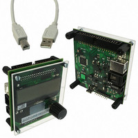
AS5030 DB
Description
BOARD DEMO AS5030
Manufacturer
austriamicrosystems
Specifications of AS5030 DB
Sensor Type
Magnetic, Rotary Position
Sensing Range
360°
Interface
USB
Voltage - Supply
5V USB or 7.5V
Embedded
Yes, MCU, 8-Bit
Utilized Ic / Part
AS5030
Lead Free Status / RoHS Status
Lead free by exemption / RoHS compliant by exemption
Sensitivity
-


AS5030
Datasheet - D e t a i l e d D e s c r i p t i o n
7.11 2-Wire Daisy Chain Mode
The AS5030 can also be connected in 2-wire Daisy Chain mode, requiring only two signals (Clock and Data) for any given number of daisy-
chained devices. Note that the connection of all devices except the last device is the same as for the 3-wire connection
device must have pin C2 (#15) set to high and feeds the DX signal to CS of the first device.
Again, each device should be buffered with a 100nF cap (shown only for the last device).
The total number of serial bits is: n*21, where n is the number of connected devices. Note that this configuration requires one extra clock (#1) to
initiate the generation of the CS signal for the first device. After reading the last device, the communication must be reset back to the first device
by introducing a timeout of CLK (no rising edge for >24µs)
Figure 19. 2-wire Daisy Chain Mode
Figure 20. Timing Diagram in 2-wire Daisy Chain Mode
www.austriamicrosystems.com/AS5030
VSS
+ 5 V
VDD
CS (#3)
CS (#1)
CS (#2)
CLK
DIO
Micro
Controller
VDD
VSS
1
Output
CMD 4
I/O
2
CMD 3
3
CMD 2
4
AS 5030 # 1
11
10
12
CMD 1
5
14
CLK
DI O
CS
C 1
CMD 0
13
AS5030
VDD
6
15
C 2
D 15
# 1
7
D 14
3
VSS
DX
8
21
D 0
Revision 2.1
22
12
11
10
CMD 4
14
23
DI O
CLK
C 1
CS
CMD 3
13
VDD
AS5030
15
24
C 2
# 2
CMD 2
25
3
VSS
CMD 1
DX
26
AS5030 # 2
CMD 0
27
D 15
28
12
11
10
D 14
14
13
DI O
C 1
29
CLK
CS
VDD
(last device)
AS5030
42
15
D 0
C 2
VSS
43
(see Figure
3
DX
CMD 4
AS5030 # 3
44
CMD 3
45
100n
17). The last
CMD 2
21 - 44
Related parts for AS5030 DB
Image
Part Number
Description
Manufacturer
Datasheet
Request
R

Part Number:
Description:
IC ENCODER ROTARY 8-BIT 16-TSSOP
Manufacturer:
austriamicrosystems
Datasheet:

Part Number:
Description:
BOARD ADAPTER AS5030
Manufacturer:
austriamicrosystems
Datasheet:
Part Number:
Description:
IC ENCODER ROTARY 8-BIT 16-TSSOP
Manufacturer:
austriamicrosystems
Datasheet:
Part Number:
Description:
8-bit High-speed Absolute Magnetic Rotary Encoder
Manufacturer:
austriamicrosystems
Datasheet:
Part Number:
Description:
IC SWITCH QUAD SPST 14-TSSOP
Manufacturer:
austriamicrosystems
Datasheet:
Part Number:
Description:
IC SWITCH QUAD SPST 14-TSSOP
Manufacturer:
austriamicrosystems
Datasheet:
Part Number:
Description:
IC AMP AUDIO MONO 1.8W 10-MSOP
Manufacturer:
austriamicrosystems
Datasheet:
Part Number:
Description:
IC AMP AUDIO MONO 1.8W 10-MSOP
Manufacturer:
austriamicrosystems
Datasheet:
Part Number:
Description:
IC AMP AUDIO MONO 1.8W 10-MSOP
Manufacturer:
austriamicrosystems
Datasheet:
Part Number:
Description:
IC AMP AUD 1.8W 3DB GAIN 10-MSOP
Manufacturer:
austriamicrosystems
Datasheet:
Part Number:
Description:
IC DRIVER LED 8-DIGIT 24-SOIC
Manufacturer:
austriamicrosystems
Datasheet:
Part Number:
Description:
IC DRIVER LED 8-DIGIT 24-SOIC
Manufacturer:
austriamicrosystems
Datasheet:
Part Number:
Description:
IC, LINE/SPEAKER PHONE CIRCUIT, SOIC-28
Manufacturer:
austriamicrosystems
Datasheet:
Part Number:
Description:
IC MULTI-STANDARD CMOS TELEPHONE SOIC-28
Manufacturer:
austriamicrosystems
Datasheet:
Part Number:
Description:
IC MULTI-STANDARD CMOS TELEPHONE SOIC-28
Manufacturer:
austriamicrosystems
Datasheet: