STEVAL-MKI109V1 STMicroelectronics, STEVAL-MKI109V1 Datasheet - Page 40
STEVAL-MKI109V1
Manufacturer Part Number
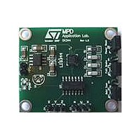
STEVAL-MKI109V1
Description
MOTEHRBOARD MEMS ADAPTER STM32
Manufacturer
STMicroelectronics
Series
MEMSr
Specifications of STEVAL-MKI109V1
Main Purpose
Motherboard; Accelerometer, Gyroscope
Embedded
Yes, MCU, 32-Bit
Utilized Ic / Part
STM32 and MEMS Demo Boards
Primary Attributes
DIL24 Socket for ST MEMS Adapter Boards
Secondary Attributes
3 V on-board linear voltage regulator
Sensing Axis
Triple Axis
Operating Voltage
5 V
Operating Current
0.68 mA
Lead Free Status / RoHS Status
Lead free / RoHS Compliant
For Use With/related Products
LIS344ALH
Other names
497-10682


Electrical characteristics
40/69
High-speed external clock generated from a crystal/ceramic resonator
The high-speed external (HSE) clock can be supplied with a 4 to 16 MHz crystal/ceramic
resonator oscillator. All the information given in this paragraph are based on characterization
results obtained with typical external components specified in
the resonator and the load capacitors have to be placed as close as possible to the oscillator
pins in order to minimize output distortion and startup stabilization time. Refer to the crystal
resonator manufacturer for more details on the resonator characteristics (frequency,
package, accuracy).
Table 21.
1. Resonator characteristics given by the crystal/ceramic resonator manufacturer.
2. Based on characterization results, not tested in production.
3. The relatively low value of the RF resistor offers a good protection against issues resulting from use in a
4. t
For C
5 pF to 25 pF range (typ.), designed for high-frequency applications, and selected to match
the requirements of the crystal or resonator (see
same size. The crystal manufacturer typically specifies a load capacitance which is the
series combination of C
can be used as a rough estimate of the combined pin and board capacitance) when sizing
C
microcontrollers” available from the ST website www.st.com.
Symbol
t
L1
f
SU(HSE)
OSC_IN
humid environment, due to the induced leakage and the bias condition change. However, it is
recommended to take this point into account if the MCU is used in tough humidity conditions.
oscillation is reached. This value is measured for a standard crystal resonator and it can vary significantly
with the crystal manufacturer
SU(HSE)
R
g
(4)
and C
C
i
2
m
F
L1
and C
is the startup time measured from the moment it is enabled (by software) to a stabilized 8 MHz
L2
Oscillator frequency
Feedback resistor
Recommended load capacitance
versus equivalent serial
resistance of the crystal (R
HSE driving current
Oscillator transconductance
Startup time
. Refer to the application note AN2867 “Oscillator design guide for ST
HSE 4-16 MHz oscillator characteristics
L2
, it is recommended to use high-quality external ceramic capacitors in the
Parameter
L1
and C
Doc ID 15056 Rev 3
L2
. PCB and MCU pin capacitance must be included (10 pF
S
)
(3)
R
V
V
Startup
V
DD
IN
S
DD
= 30
= V
= 3.3 V
is stabilized
Conditions
SS
Figure
with 30 pF load
(1)(2)
18). C
STM32F102x8, STM32F102xB
Table
L1
and C
Min
21. In the application,
25
4
L2
are usually the
Typ
200
30
8
2
Max
16
1
mA/V
MHz
Unit
mA
k
ms
pF
Related parts for STEVAL-MKI109V1
Image
Part Number
Description
Manufacturer
Datasheet
Request
R

Part Number:
Description:
BOARD EVAL FOR MEMS SENSORS
Manufacturer:
STMicroelectronics
Datasheet:

Part Number:
Description:
EVALBOARD/STEVAL-ISV014V1
Manufacturer:
STMicroelectronics
Part Number:
Description:
BOARD EVAL FOR ST802RT1
Manufacturer:
STMicroelectronics
Datasheet:

Part Number:
Description:
BOARD EVAL FOR VACUUM CLEANER
Manufacturer:
STMicroelectronics
Datasheet:

Part Number:
Description:
KIT DEV STARTER ST10F276Z5
Manufacturer:
STMicroelectronics
Datasheet:

Part Number:
Description:
BOARD LED CTLR/DVR STLED316S
Manufacturer:
STMicroelectronics
Datasheet:

Part Number:
Description:
BOARD EVAL BLDC SENSORLESS MOTOR
Manufacturer:
STMicroelectronics
Datasheet:

Part Number:
Description:
BOARD ELECT FISCAL CASH REGISTER
Manufacturer:
STMicroelectronics
Datasheet:

Part Number:
Description:
BOARD EVAL BIPO SOLUTION FOR PFC
Manufacturer:
STMicroelectronics
Datasheet:

Part Number:
Description:
BOARD EVAL UPS 450W VOUT=220V
Manufacturer:
STMicroelectronics
Datasheet:
Part Number:
Description:
STMicroelectronics [RIPPLE-CARRY BINARY COUNTER/DIVIDERS]
Manufacturer:
STMicroelectronics
Datasheet:
Part Number:
Description:
STMicroelectronics [LIQUID-CRYSTAL DISPLAY DRIVERS]
Manufacturer:
STMicroelectronics
Datasheet:
Part Number:
Description:
BOARD EVAL FOR MEMS SENSORS
Manufacturer:
STMicroelectronics
Datasheet: