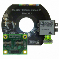
ADIS16365/PCBZ Analog Devices Inc, ADIS16365/PCBZ Datasheet - Page 13

ADIS16365/PCBZ
Manufacturer Part Number
ADIS16365/PCBZ
Description
BOARD INTERFACE FOR ADIS16365
Manufacturer
Analog Devices Inc
Series
iMEMS®, iSensor™r
Specifications of ADIS16365/PCBZ
Sensor Type
Accelerometer, Gyroscope, 3 Axis
Sensing Range
±17g, ±75°/sec, ±150°/sec, ±300°/sec
Interface
SPI Serial
Sensitivity
3.3mg/LSB, 0.0125 ~ 0.05°/sec/LSB
Voltage - Supply
4.75 V ~ 5.25 V
Embedded
No
Utilized Ic / Part
ADIS16365
Silicon Manufacturer
Analog Devices
Application Sub Type
Accelerometer / Gyroscope
Kit Application Type
Sensing - Motion / Vibration / Shock
Silicon Core Number
ADIS16365
Lead Free Status / RoHS Status
Not applicable / RoHS Compliant
For Use With
ADISUSBZ - KIT EVAL ADIS W/SOFTWARE USB
Lead Free Status / RoHS Status
Lead free / RoHS Compliant, Not applicable / RoHS Compliant
Power Management
Setting SMPL_PRD ≥ 0x0A also sets the sensor to low power
mode. For systems that require lower power dissipation, in-
system characterization helps users to quantify the associated
performance trade-offs. In addition to sensor performance, this
mode affects SPI data rates (see Table 2). Set SLP_CNT[8] = 1
(DIN = 0xBB01) to start the indefinite sleep mode, which requires
a CS assertion (high to low), reset, or power cycle to wake up.
Use SLP_CNT[7:0] to put the device into sleep mode for a
specified period. For example, SLP_CNT[7:0] = 0x64 (DIN =
0xBA64) puts the ADIS16360/ADIS16365 to sleep for 50 sec.
Table 19. SLP_CNT Bit Descriptions
Bits
[15:9]
[8]
[7:0]
Sensor Bandwidth
The signal chain for each MEMS sensor has several filter stages,
which shape their frequency response. Figure 14 provides a
block diagram for both gyroscope and accelerometer signal
paths. Table 20 provides additional information for digital filter
configuration.
Digital Filtering
The N blocks in Figure 14 are part of the programmable low-pass
filter, which provides additional noise reduction on the inertial
sensor outputs. This filter contains two cascaded averaging filters
that provide a Bartlett window, FIR filter response (see Figure 15).
For example, set SENS_AVG[2:0] = 100 (DIN = 0xB804) to set
each stage to 16 taps. When used with the default sample rate of
819.2 SPS, this value reduces the sensor bandwidth to approxi-
mately 16 Hz.
GYROSCOPE
SENSOR
ACCELERATION
FROM
Description (Default = 0x0000)
Not used
Indefinite sleep mode; set to 1
Programmable sleep time bits, 0.5 sec/LSB
SENSOR
FROM
Figure 14. MEMS Analog and Digital Filters
404Hz
LPF
757Hz
330Hz
LPF
LPF
N = 2
m = SENS_AVG[2:0]
N
N
m
N
N
Rev. D | Page 13 of 20
Dynamic Range
The SENS_AVG[10:8] bits provide three dynamic range settings
for this gyroscope. The lower dynamic range settings (±75°/sec
and ±150°/sec) limit the minimum filter tap sizes to maintain
resolution. For example, set SENS_AVG[10:8] = 010 (DIN =
0xB902) for a measurement range of ±150°/sec. Because this
setting can influence the filter settings, program SENS_AVG[10:8]
and then SENS_AVG[2:0] if more filtering is required.
Table 20. SENS_AVG Bit Descriptions
Bits
[15:11]
[10:8]
[7:3]
[2:0]
–100
–120
–140
–20
–40
–60
–80
Figure 15. Bartlett Window, FIR Filter Frequency Response
0.001
0
Description (Default = 0x0402)
Not used
Measurement range (sensitivity) selection
100 = ±300°/sec (default condition)
010 = ±150°/sec, filter taps ≥ 4 (Bits[2:0] ≥ 0x02)
001 = ±75°/sec, filter taps ≥ 16 (Bits[2:0] ≥ 0x04)
Not used
Number of taps in each stage; value of m in N = 2
N = 2
N = 4
N = 16
N = 64
(Phase Delay = N Samples)
0.01
FREQUENCY (
ADIS16360/ADIS16365
f
/
f
S
)
0.1
1
m


