STEVAL-ISA056V1 STMicroelectronics, STEVAL-ISA056V1 Datasheet - Page 52
STEVAL-ISA056V1
Manufacturer Part Number
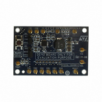
STEVAL-ISA056V1
Description
BOARD EVAL BASED ON PM6600
Manufacturer
STMicroelectronics
Type
PWM Controllersr
Specifications of STEVAL-ISA056V1
Design Resources
STEVAL-ISA056V1 Gerber Files STEVAL-ISA056V1 Schematic STEVAL-ISA056V1 Bill of Material
Current - Output / Channel
30mA
Outputs And Type
6, Non-Isolated
Voltage - Output
36 V
Features
Dimmable
Voltage - Input
4.5 ~ 28V
Utilized Ic / Part
PM6600
Input Voltage
4.5 V to 28 V
Output Voltage
36 V
Product
Power Management Modules
Core Chip
PM6600
Topology
Boost
No. Of Outputs
1
Dimming Control Type
PWM
Mcu Supported Families
PM6600
Lead Free Status / RoHS Status
Lead free / RoHS Compliant
For Use With/related Products
PM6600
Other names
497-8414
Available stocks
Company
Part Number
Manufacturer
Quantity
Price
Company:

Part Number:
STEVAL-ISA056V1
Manufacturer:
STMicroelectronics
Quantity:
1


Application note
B.4.5
B.4.6
52/60
defining D
The worst case for the output voltage ripple is when input voltage is lower (V
A simple way to select the C
In order to affect as less as possible the current generators, it would be better to fix the
maximum ripple lower than the typical voltage across the generators.
For example considering ΔV
leading generator), the required capacitance is:
Equation 35
A margin from the calculated value should be taken into account because of the
capacitance drop due to the applied voltage when MLCCs are used.
A 4.7 µF MLCC can be a good choice for this application (two 2.2 μF MLCC in parallel can
be also a good solution).
In case a dimming duty cycle different from 100% is used, a further contribution to the
capacitor discharge (during the off time of the dimming cycle) should be considered.
Input capacitor choice
The input capacitor of a boost converter is less critical than the output capacitor, due to the
fact that the inductor is in series with the input, and hence, the input current waveform is
continuous.
A low ESR capacitor is always recommended.
A capacitor of 10 µF is tentatively a good choice for most of the applications.
Overvoltage protection divider setting
The overvoltage protection (OVP) divider provides a partition of the output voltage to the
OVSEL pin. The OVP divider setting not only fixes the OVP threshold, but also the open-
channel detection threshold (93% of the OVP threshold).
The proper OVP divider setting can be calculated by the equation:
Equation 36
2
as:
D
2
=
C
2
OUT
OUT
R
OUT
⋅
F
0
Doc ID 14248 Rev 7
SW
⋅
lower than 80 mV (i.e. the 20% of the voltage across the
value is fixing a maximum voltage ripple.
(
M
>
⋅
L
(
−
I
R
, L
⋅
1
peak
M
1
)
2
=
Δ ⋅
=
R
−
⎧
⎨
⎩
V
2
I
. 0
OUT
⎛
⎜
⎝
OUT
. 0
. 1
263
V
OVP
23
235
,
max
)
⋅
T
OFF
@
−
@
1
⎞
⎟
⎠
=
V
V
. 2
IN
IN
,
,
02
max
min
μ
F
=
=
9
14
6 .
4 .
V
V
IN,min
= 9.6 V).
PM6600
Related parts for STEVAL-ISA056V1
Image
Part Number
Description
Manufacturer
Datasheet
Request
R

Part Number:
Description:
BOARD RGB CTR ST7,STP08C596MTR
Manufacturer:
STMicroelectronics
Datasheet:

Part Number:
Description:
Power Management IC Development Tools Full Speed USB to RS232 Bridge Demo
Manufacturer:
STMicroelectronics
Datasheet:
Part Number:
Description:
Power Management IC Development Tools 2.5W solar eval BRD USB SPV1040 LD39050
Manufacturer:
STMicroelectronics
Datasheet:

Part Number:
Description:
BOARD EVAL FOR MEMS SENSORS
Manufacturer:
STMicroelectronics
Datasheet:

Part Number:
Description:
KIT DEV STARTER ST10F276Z5
Manufacturer:
STMicroelectronics
Datasheet:

Part Number:
Description:
BOARD EVAL HDMI $ VIDEO SWITCH
Manufacturer:
STMicroelectronics
Datasheet:

Part Number:
Description:
BOARD DEMO ACCELEROMETER DIL24
Manufacturer:
STMicroelectronics
Datasheet:

Part Number:
Description:
BOARD STLM75/STDS75/ST72F651
Manufacturer:
STMicroelectronics
Datasheet:

Part Number:
Description:
EVAL BOARD 3AXIS MEMS ACCELLRMTR
Manufacturer:
STMicroelectronics
Datasheet:

Part Number:
Description:
BOARD EVAL 8BIT MICRO + TDE1708
Manufacturer:
STMicroelectronics
Datasheet:
Part Number:
Description:
STMicroelectronics [RIPPLE-CARRY BINARY COUNTER/DIVIDERS]
Manufacturer:
STMicroelectronics
Datasheet:
Part Number:
Description:
STMicroelectronics [LIQUID-CRYSTAL DISPLAY DRIVERS]
Manufacturer:
STMicroelectronics
Datasheet:
Part Number:
Description:
BOARD EVAL FOR MEMS SENSORS
Manufacturer:
STMicroelectronics
Datasheet: