STEVAL-ISA043V2 STMicroelectronics, STEVAL-ISA043V2 Datasheet

BOARD EVAL BASED ON ST1S06

STEVAL-ISA043V2

Manufacturer Part Number
STEVAL-ISA043V2
Description
BOARD EVAL BASED ON ST1S06
Manufacturer
STMicroelectronics

Specifications of STEVAL-ISA043V2

Main Purpose
DC/DC, Step Down
Outputs And Type
1, Non-Isolated
Voltage - Output
3.3V
Current - Output
1.5A
Voltage - Input
2.7 ~ 6V
Regulator Topology
Buck
Frequency - Switching
1.5MHz
Board Type
Fully Populated
Utilized Ic / Part
ST1S06
Product
Power Management Modules
Silicon Manufacturer
ST Micro
Silicon Core Number
ST1S06PUR
Kit Application Type
Power Management - Voltage Regulator
Application Sub Type
Synchronous Buck Converter
Kit Contents
Board
Rohs Compliant
Yes
Lead Free Status / RoHS Status
Lead free / RoHS Compliant
Power - Output
-
Lead Free Status / Rohs Status
Lead free / RoHS Compliant
Other names
497-6420
STEVAL-ISA043V2

Available stocks

Company
Part Number
Manufacturer
Quantity
Price
Part Number:
STEVAL-ISA043V2
Manufacturer:
STMicroelectronics
Quantity:
1
March 2008
Introduction
The ST1S06 is an adjustable current mode pulse width modulation (PWM) synchronous,
step down DC-DC converter with inhibit function. It is optimized for powering all low-voltage
applications and, generally, to replace the high current linear solution when the power
dissipation may cause overheating of the application environment.
It provides up to 1.5 A over an input voltage range of 2.5 V to 5.5 V. A high switching
frequency (1.5 MHz) enables the use of tiny surface-mount components (SMD). In addition
to the resistor divider used to set the output voltage value, only an inductor and two
capacitors are required. Moreover, low output ripple is guaranteed by the current mode
PWM topology and by the use of low series resistance (ESR) SMD ceramic capacitors.
The device is thermal protected and current limited to prevent damage due to accidental
short circuits. It is a complete 1.5 A switching regulator with its internal compensation
eliminating the need for additional components. The constant frequency, current mode,
PWM architecture and stable operation with ceramic capacitors results in a low, predictable
output ripple. To clamp the error amplifier reference voltage, this device includes a Soft Start
control block generating a voltage ramp.
The ST1S06 is available in 6L-DFN 3x3 package
Moreover, an on-chip power on reset of 50 = 100 µs ensures correct performance when
switching on the power supply. Other circuits fitted to the device protection are the Thermal
Shut down block which turn-off the regulator when the junction temperature exceeds 150°C
typically and the Cycle- by-cycle Current Limiting that provides protection against shorted
outputs. Being the ST1S06 an adjustable regulator, the output voltage is determined by an
external resistor divider. The desired value is given by the following equation:
Equation 1
Due to the high switching frequency and peak current, it is important to optimize the
application environment by reducing the length of the PCB traces and placing all the
external component near the device. The chosen inductor must not saturate at the peak
current level. Moreover, its value can be selected keeping in account that a large inductor
value increases the efficiency at low output current and reduces output voltage ripple, while
a smaller inductor can be chosen when it is important to reduce the package size and the
total cost of the application.
Finally, the ST1S06 is designed to work properly with X5R or X7R SMD ceramic capacitors
both at the input and at the output. These types of capacitors, thanks to their very low series
resistance (ESR), minimize the output voltage ripple. Other low ESR capacitors values can
be used depending on application requirements without invalidating correct device
performance.
high frequency synchronous buck converter
V
Rev 2
OUT
=
V
FB
1
+
R
------ -
R
1
2
Application note
AN2371
ST1S06
www.st.com
1/12

Related parts for STEVAL-ISA043V2

STEVAL-ISA043V2 Summary of contents

Page 1

Introduction The ST1S06 is an adjustable current mode pulse width modulation (PWM) synchronous, step down DC-DC converter with inhibit function optimized for powering all low-voltage applications and, generally, to replace the high current linear solution when the power ...

Page 2

Contents Contents 1 Selecting components for your application . . . . . . . . . . . . . . . . . . . . . . 4 1.1 Input capacitor . . . . . . ...

Page 3

AN2371 List of figures Figure 1. Simplified schematic . . . . . . . . . . . . . . . . . . . . . . . . . . . . . . . . ...

Page 4

Selecting components for your application 1 Selecting components for your application This section provides information to help you select the best-adapted components for your application. Figure 1. Simplified schematic 1.1 Input capacitor The input capacitor must be able to support ...

Page 5

AN2371 The maximum and minimum duty cycles are: Equation 3 Equation 4 Where V is the voltage drop across the internal NMOS and VSW the voltage drop across F the internal PDMOS. Considering the range DMIN to DMAX ...

Page 6

Thermal considerations 2 Thermal considerations The dissipated power of the device is related to three different sources: 1. Switch losses due to the not negligible R Equation 7 Equation 8 Where D is the duty cycle of the application. Note ...

Page 7

AN2371 3 Short-circuit protection In Over-current Protection mode, when the peak current reaches the current limit, the device reduces the t to its minimum value. In these conditions, the duty cycle is strongly reduced ON and, in most of the ...

Page 8

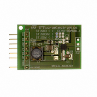
Board usage recommendation 4 Board usage recommendation The board shown in you have two lines available; one used to supply or sink current and the other one used to perform the needed measurement. Figure 2. ST1S06 board picture Figure 3. ...

Page 9

AN2371 4.1 External component selection Figure 5 shows the typical application used to obtain an output voltage of 1.2 V. Figure 5. ST1S06 application schematic Vin In order to obtain the needed output voltage, we must choose the resistor divider ...

Page 10

Board usage recommendation 4.3 Capacitors selection It is possible to use any X5R or X7R ceramic capacitor – 4.7 µF (ceramic) or higher without limit – µF (ceramic) or higher possible to use ...

Page 11

AN2371 5 Bill of materials Table 1. BOM with most often used components Name C1 4.7 µ µF C3 3.3 µH L 4.7 µH 6 Revision history Table 2. Document revision history Date 19-Jun-2006 20-Mar-2008 Value Material Ceramic ...

Page 12

... Information in this document is provided solely in connection with ST products. STMicroelectronics NV and its subsidiaries (“ST”) reserve the right to make changes, corrections, modifications or improvements, to this document, and the products and services described herein at any time, without notice. All ST products are sold pursuant to ST’s terms and conditions of sale. ...

Related keywords