LM20144EVAL National Semiconductor, LM20144EVAL Datasheet

BOARD EVAL 4A POWERWISE LM20144

LM20144EVAL

Manufacturer Part Number
LM20144EVAL
Description
BOARD EVAL 4A POWERWISE LM20144
Manufacturer
National Semiconductor
Series
PowerWise®r
Datasheets

Specifications of LM20144EVAL

Main Purpose
DC/DC, Step Down
Outputs And Type
1, Non-Isolated
Voltage - Output
1.2V
Current - Output
4A
Voltage - Input
2.95 ~ 5.5V
Regulator Topology
Buck
Frequency - Switching
1MHz
Board Type
Fully Populated
Utilized Ic / Part
LM20144
Lead Free Status / RoHS Status
Not applicable / Not applicable
Power - Output
-
© 2007 National Semiconductor Corporation
LM20144 Evaluation Board
Introduction
The LM20144 is a full featured buck switching regulator ca-
pable of driving up to 4A of load current. The switching fre-
quency of the LM20144 can be varied from 500kHz to 1.5Mhz
with an external resistor allowing the size of the power stage
components to be reduced while still providing efficient oper-
ation. The LM20144 is capable of converting an input voltage
between 2.95V and 5.5V down to an output voltage as low as
0.8V. Fault protection features include cycle-by-cycle current
limit, output power good, and output over-voltage protection.
The dual function soft-start/tracking pin can be used to control
the startup response of the LM20144, and the precision en-
able pin can be used to easily sequence the LM20144 in
applications with sequencing requirements. The LM20144 is
available in an eTSSOP-16 package with an exposed pad for
enhanced thermal performance.
300330
FIGURE 1. Evaluation Board Schematic
National Semiconductor
Application Note 1692
Dennis Hudgins
October 30, 2007
The LM20144 evaluation board has been designed to bal-
ance overall solution size with the efficiency of the regulator.
The evaluation board measures just under 1.3” x 1.1” on a
two layer PCB, with all components placed on the top layer.
The power stage and compensation components of the
LM20144 evaluation board have been optimized for an input
voltage of 5V and a switching frequency of 1 MHz, but for
testing purposes, the input can be varied across the entire
operating range. The output voltage of the evaluation board
is nominally 1.2V, but this voltage can be easily changed by
replacing one of the feedback resistors (R
control loop compensation of the LM20144 evaluation board
has been designed to provide a stable solution over the entire
input and output voltage range with a reasonable transient
response. The EN pin must be above 1.18V (typ) on the board
to initiate switching. If the EN function is not necessary, the
EN pin should be externally tied to V
IN
30033001
.
FB1
www.national.com
or R
FB2
). The

Related parts for LM20144EVAL

LM20144EVAL Summary of contents

Page 1

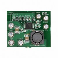
... The LM20144 is available in an eTSSOP-16 package with an exposed pad for enhanced thermal performance.     © 2007 National Semiconductor Corporation National Semiconductor Application Note 1692 Dennis Hudgins October 30, 2007 The LM20144 evaluation board has been designed to bal- ance overall solution size with the efficiency of the regulator. The evaluation board measures just under 1.3” ...

Page 2

... This terminal connects to the power good output of the device. There kΩ pull-up resistor from this pin to the input voltage. The voltage on this pin should not exceed 5.5V during normal operation and has an absolute maximum voltage rating of 6V. 2 Qty Manufacturer 1 National Semiconductor 1 Murata 1 Murata 1 Murata ...

Page 3

Performance Characteristics Efficiency vs Load Load Regulation (V IN 30033015 = 5V) 0. Load Transient Response 30033017 Startup Waveform (2ms/DIV) 30033020 3 Line Regulation (I = 4A) LOAD 30033016 (200 µs/DIV) 30033019 www.national.com ...

Page 4

Component Selection This section provides a walk-through of the design process of the LM20144 evaluation board. Unless otherwise indicated all equations assume units of Amps (A) for current, Farads (F) for capacitance, Henries (H) for inductance, and Volts (V) for ...

Page 5

C the value for R as outlined in the next section Once the value known, resistor zero in the control loop to cancel ...

Page 6

PCB Layout www.national.com Top Layer Bottom Layer 6 30033013 30033014 ...

Page 7

Notes 7 www.national.com ...

Page 8

... For more National Semiconductor product information and proven design tools, visit the following Web sites at: Products Amplifiers www.national.com/amplifiers Audio www.national.com/audio Clock Conditioners www.national.com/timing Data Converters www.national.com/adc Displays www.national.com/displays Ethernet www.national.com/ethernet Interface www.national.com/interface LVDS www.national.com/lvds Power Management www.national.com/power Switching Regulators www.national.com/switchers LDOs www ...

Related keywords