STEVAL-ISA051V1 STMicroelectronics, STEVAL-ISA051V1 Datasheet - Page 41
STEVAL-ISA051V1
Manufacturer Part Number
STEVAL-ISA051V1
Description
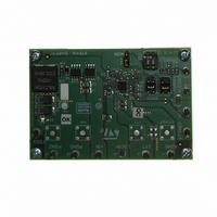
BOARD EVAL PM6670S DDR2/3
Manufacturer
STMicroelectronics
Type
DC/DC Switching Converters, Regulators & Controllersr
Specifications of STEVAL-ISA051V1
Design Resources
STEVAL-ISA051V1 Gerber Files STEVAL-ISA051V1 Schematic STEVAL-ISA051V1 Bill of Material
Main Purpose
Special Purpose DC/DC, DDR Memory Supply
Outputs And Type
4, Non-Isolated
Voltage - Output
1.5V, 1.8V
Voltage - Input
4.5 ~ 28V
Regulator Topology
Buck
Board Type
Fully Populated
Utilized Ic / Part
PM6670
Input Voltage
4.5 V to 28 V
Output Voltage
1.8 V, 1.5 V
Product
Power Management Modules
Silicon Manufacturer
ST Micro
Silicon Core Number
PM6670S
Kit Application Type
Power Management
Application Sub Type
DDR2/3 Memory Power Supply Controller
Kit Contents
Board
Lead Free Status / RoHS Status
Lead free / RoHS Compliant
Current - Output
-
Power - Output
-
Frequency - Switching
-
Lead Free Status / Rohs Status
Lead free / RoHS Compliant
For Use With/related Products
PM6670S
Other names
497-8411
Available stocks
Company
Part Number
Manufacturer
Quantity
Price
Company:

Part Number:
STEVAL-ISA051V1
Manufacturer:
STMicroelectronics
Quantity:
1


PM6670S
8.1.1
Inductor selection
Once the switching frequency has been defined, the inductance value depends on the
desired inductor ripple current. Low inductance value means great ripple current that brings
poor efficiency and great output noise. On the other hand a great current ripple is desirable
for fast transient response when a load step is applied.
High inductance brings higher efficiency, but the transient response is critical, especially if
V
system stability and jitter-free operations (see output capacitor selection paragraph). The
product of the output capacitor's ESR multiplied by the inductor ripple current must be taken
into consideration. A good trade-off between the transient response time, the efficiency, the
cost and the size is choosing the inductance value in order to maintain the inductor ripple
current between 20 % and 50 % (usually 40 %) of the maximum output current.
The maximum inductor ripple current, ΔI
Given these considerations, the inductance value can be calculated with the following
expression:
Equation 29
where f
ΔI
Once the inductor value is determined, the inductor ripple current is then recalculated:
Equation 30
The next step is the calculation of the maximum r.m.s. inductor current:
Equation 31
The inductor must have an r.m.s. current greater than I
stability.
Then the calculation of the maximum inductor peak current follows:
Equation 32
I
L,PEAK
INmin
L
is the inductor ripple current.
- V
SW
is important in inductor selection in term of its saturation current.
OUT
is the switching frequency, V
is small. Moreover a minimum output ripple voltage is necessary to assure
I
Δ
, L
Doc ID 14432 Rev 4
RMS
I
, L
I
MAX
, L
PEAK
L
=
=
=
I (
IN
V
V
=
LOAD
L,MAX
fsw
IN
IN
I
is the input voltage, V
LOAD
,
MAX
−
fsw
Δ ⋅
,
V
MAX
, occurs at the maximum input voltage.
OUT
,
MAX
I
−
L
⋅
L
)
V
2
OUT
⋅
+
+
V
V
Δ
(
OUT
Δ
IN
I
⋅
, L
I
L,RMS
V
, L
2
MAX
V
12
IN
MAX
OUT
,
MAX
)
in order to assure thermal
2
OUT
Application information
is the output voltage and
41/54
Related parts for STEVAL-ISA051V1
Image
Part Number
Description
Manufacturer
Datasheet
Request
R

Part Number:
Description:
BOARD RGB CTR ST7,STP08C596MTR
Manufacturer:
STMicroelectronics
Datasheet:

Part Number:
Description:
Power Management IC Development Tools Full Speed USB to RS232 Bridge Demo
Manufacturer:
STMicroelectronics
Datasheet:
Part Number:
Description:
Power Management IC Development Tools 2.5W solar eval BRD USB SPV1040 LD39050
Manufacturer:
STMicroelectronics
Datasheet:

Part Number:
Description:
BOARD EVAL FOR MEMS SENSORS
Manufacturer:
STMicroelectronics
Datasheet:

Part Number:
Description:
KIT DEV STARTER ST10F276Z5
Manufacturer:
STMicroelectronics
Datasheet:

Part Number:
Description:
BOARD EVAL HDMI $ VIDEO SWITCH
Manufacturer:
STMicroelectronics
Datasheet:

Part Number:
Description:
BOARD DEMO ACCELEROMETER DIL24
Manufacturer:
STMicroelectronics
Datasheet:

Part Number:
Description:
BOARD STLM75/STDS75/ST72F651
Manufacturer:
STMicroelectronics
Datasheet:

Part Number:
Description:
EVAL BOARD 3AXIS MEMS ACCELLRMTR
Manufacturer:
STMicroelectronics
Datasheet:

Part Number:
Description:
BOARD EVAL 8BIT MICRO + TDE1708
Manufacturer:
STMicroelectronics
Datasheet:
Part Number:
Description:
STMicroelectronics [RIPPLE-CARRY BINARY COUNTER/DIVIDERS]
Manufacturer:
STMicroelectronics
Datasheet:
Part Number:
Description:
STMicroelectronics [LIQUID-CRYSTAL DISPLAY DRIVERS]
Manufacturer:
STMicroelectronics
Datasheet:
Part Number:
Description:
BOARD EVAL FOR MEMS SENSORS
Manufacturer:
STMicroelectronics
Datasheet: