STEVAL-IFW001V1 STMicroelectronics, STEVAL-IFW001V1 Datasheet - Page 29
STEVAL-IFW001V1
Manufacturer Part Number
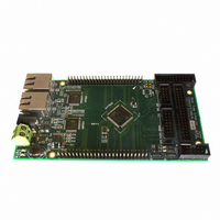
STEVAL-IFW001V1
Description
BOARD EVAL BASED ON STR912FA
Manufacturer
STMicroelectronics
Datasheets
1.STEVAL-IFW001V1.pdf
(102 pages)
2.STEVAL-IFW001V1.pdf
(9 pages)
3.STEVAL-IFW001V1.pdf
(7 pages)
Specifications of STEVAL-IFW001V1
Design Resources
STEVAL-IFW001V1 Gerber Files STEVAL-IFW001V1 Schematic STEVAL-IFW001V1 Bill of Material
Main Purpose
Interface, Ethernet
Embedded
Yes, MCU, 32-Bit
Utilized Ic / Part
E-STE101P, STR912FAW44
Primary Attributes
Dual Ethernet Transceivers for Full Duplex Communication
Secondary Attributes
Up to 32 MII Addresses, UART, I2C, SPI, with RJ45 Connectors
Silicon Manufacturer
ST Micro
Core Architecture
ARM
Core Sub-architecture
ARM9
Silicon Core Number
STR9
Silicon Family Name
STR91x
For Use With
497-8263 - BOARD EXTENSION STEVAL-IFW001V1
Lead Free Status / RoHS Status
Lead free / RoHS Compliant
Other names
497-8262


STR91xFAxxx
3.15.2
3.15.3
3.15.4
Boundary scan
Standard JTAG boundary scan testing compliant with IEEE-1149.1 is available on the
majority of pins of the STR91xFA for circuit board test during manufacture of the end
product. STR91xFA pins that are not serviced by boundary scan are the following:
●
●
●
CPU debug
The ARM966E-S CPU core has standard ARM EmbeddedICE-RT logic, allowing the
STR91xFA to be debugged through the JTAG interface. This provides advanced debugging
features making it easier to develop application firmware, operating systems, and the
hardware itself. Debugging requires that an external host computer, running debug software,
is connected to the STR91xFA target system via hardware which converts the stream of
debug data and commands from the host system’s protocol (USB, Ethernet, etc.) to the
JTAG EmbeddedICE-RT protocol on the STR91xFA. These protocol converters are
commercially available and operate with debugging software tools.
The CPU may be forced into a Debug State by a breakpoint (code fetch), a watchpoint (data
access), or an external debug request over the JTAG channel, at which time the CPU core
and memory system are effectively stopped and isolated from the rest of the system. This is
known as Halt Mode and allows the internal state of the CPU core, memory, and peripherals
to be examined and manipulated. Typical debug functions are supported such as run, halt,
and single-step. The EmbeddedICE-RT logic supports two hardware compare units. Each
can be configured to be either a watchpoint or a breakpoint. Breakpoints can also be data-
dependent.
Debugging (with some limitations) may also occur through the JTAG interface while the CPU
is running full speed, known as Monitor Mode. In this case, a breakpoint or watchpoint will
not force a Debug State and halt the CPU, but instead will cause an exception which can be
tracked by the external host computer running monitor software. Data can be sent and
received over the JTAG channel without affecting normal instruction execution. Time critical
code, such as Interrupt Service Routines may be debugged real-time using Monitor Mode.
JTAG security bit
This is a non-volatile bit (Flash memory based), which when set will not allow the JTAG
debugger or JTAG programmer to read the Flash memory contents.
Using JTAG ISP, this bit is typically programmed during manufacture of the end product to
prevent unwanted future access to firmware intellectual property. The JTAG Security Bit can
be cleared only by a JTAG “Full Chip Erase” command, making the STR91xFA device blank
(except for programmed OTP bytes), and ready for programming again. The CPU can read
the status of the JTAG Security Bit, but it may not change the bit value.
JTAG pins JTCK, JTMS, JTDI, JTDO, JTRSTn, JRTCK
Oscillator input pins X1_CPU, X2_CPU, X1_RTC, X2_RTC
Tamper detect input pin TAMPER_IN (128-pin and 144-pin packages only)
Doc ID 13495 Rev 6
Functional overview
29/102
Related parts for STEVAL-IFW001V1
Image
Part Number
Description
Manufacturer
Datasheet
Request
R

Part Number:
Description:
BOARD EVAL SPZB260 MOD FOR STR9
Manufacturer:
STMicroelectronics
Datasheet:

Part Number:
Description:
BOARD EVAL EXTENSION SN250
Manufacturer:
STMicroelectronics
Datasheet:

Part Number:
Description:
BOARD EVAL AB-54003L-512
Manufacturer:
STMicroelectronics
Datasheet:

Part Number:
Description:
BOARD REF DESIGN RF DMOS PWR AMP
Manufacturer:
STMicroelectronics
Datasheet:

Part Number:
Description:
BOARD EVAL PWR AMP AB-84008L-470
Manufacturer:
STMicroelectronics
Datasheet:

Part Number:
Description:
BOARD EVAL FOR STM32F103XX
Manufacturer:
STMicroelectronics
Datasheet:

Part Number:
Description:
BOARD EVAL AB-54003L-512
Manufacturer:
STMicroelectronics
Datasheet:

Part Number:
Description:
BOARD SMART PLUG STM32 SPZB260PR
Manufacturer:
STMicroelectronics
Datasheet:

Part Number:
Description:
BOARD DEMO BLUETOOTH SPBT2532C2
Manufacturer:
STMicroelectronics
Datasheet:
Part Number:
Description:
ZIGBEE USB DONGLE EVAL KIT
Manufacturer:
STMicroelectronics
Datasheet:
Part Number:
Description:
STMicroelectronics [RIPPLE-CARRY BINARY COUNTER/DIVIDERS]
Manufacturer:
STMicroelectronics
Datasheet:
Part Number:
Description:
STMicroelectronics [LIQUID-CRYSTAL DISPLAY DRIVERS]
Manufacturer:
STMicroelectronics
Datasheet:

Part Number:
Description:
BOARD EVAL FOR MEMS SENSORS
Manufacturer:
STMicroelectronics
Datasheet: