CDB5467U Cirrus Logic Inc, CDB5467U Datasheet - Page 36
CDB5467U
Manufacturer Part Number
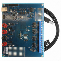
CDB5467U
Description
BOARD EVAL FOR CS5467 ADC
Manufacturer
Cirrus Logic Inc
Type
A/Dr
Specifications of CDB5467U
Main Purpose
Power Management, Energy/Power Meter
Embedded
Yes, MCU, 8-Bit
Utilized Ic / Part
CS5467
Primary Attributes
Watt-Hour Meter
Secondary Attributes
Graphical User Interface, SPI™ & USB Interfaces
Product
Data Conversion Development Tools
Maximum Clock Frequency
4 MHz
Interface Type
USB
Supply Voltage (max)
5 V
Supply Voltage (min)
3.3 V
For Use With/related Products
CS5467
Lead Free Status / RoHS Status
Contains lead / RoHS non-compliant
Lead Free Status / RoHS Status
Lead free / RoHS Compliant, Contains lead / RoHS non-compliant
Other names
598-1555
CDB-5467U
CDB-5467U


8.3.6 Line to Sample Frequency Ratio (Epsilon)
8.3.7 Pulse Output Width (PulseWidth)
8.3.8 Pulse Output Rate (PulseRate)
8.3.9 Cycle Count (N)
8.3.10 Wideband Reactive Power (Q1
36
MSB
MSB
MSB
MSB
MSB
-(2
-(2
-(2
0
0
0
Default = 0.0125 (4.0 kHz x 0.0125 or 50 Hz)
Epsilon is the ratio of the input line frequency to the output word rate (OWR). It can either be written by the ap-
plication program or calculated automatically from the line frequency (from the voltage input) using the AFC bit
in the Modes register. It is a two's complement value in the range of -1.0 ≤ value < 1.0, with the binary point to
the right of the MSB. Negative values are not used.
0
0
Default = 1 (250 uS at OWR = 4 kHz)
PulseWidth sets the duration of energy pulses. The actual pulse duration is the contents of PulseWidth divided
by the output word rate (OWR). PulseWidth is an integer in the range of 1 to 8,388,607.
Default= -1
PulseRate sets the full-scale frequency for E1, E2, E3 pulse outputs. For a 4 kHz sample rate, the maximum
pulse rate is 2 kHz. This is a two's complement value in the range of -1 ≤ value < 1, with the binary point to the
left of the MSB.
Refer to
)
)
)
Default = 4000
Determines the number of output word rate (OWR) samples to use in calculating low-rate results. Cycle Count
( N ) is an integer in the range of 10 to 8,388,607. Values less than 10 should not be used.
Address: 20 ( Q1
Wideband reactive power is calculated using vector subtraction. (See
on page 16). The value is signed, but has a range of 0 ≤ value < 1.0. The binary point is to the right of the MSB.
2
2
2
2
2
22
22
-1
-1
-1
6.10 Energy Pulse Rate
2
2
2
2
2
21
21
-2
-2
-2
WB
2
2
2
2
2
20
20
-3
-3
-3
–
), 21 ( Q2
Address: 19
2
2
2
2
2
19
19
-4
-4
-4
WB
on page 21 for more information.
2
2
2
2
2
)
18
18
-5
-5
-5
–
WB
Address: 15
–
2
2
2
2
2
Address: 14
17
17
-6
-6
-6
, Q2
WB
2
2
2
2
2
16
16
-7
-7
-7
–
)
Address: 17
.....
.....
.....
.....
.....
2
2
2
2
2
-17
-17
-17
6
6
2
2
2
2
2
-18
-18
-18
5
5
Section 4.8 Power and Energy Results
2
2
2
2
2
-19
-19
-19
4
4
2
2
2
2
2
-20
-20
-20
3
3
2
2
2
2
2
-21
-21
-21
2
2
CS5467
2
2
2
2
2
-22
-22
-22
1
1
DS714F1
LSB
LSB
LSB
LSB
LSB
2
2
2
2
2
-23
-23
-23
0
0
Related parts for CDB5467U
Image
Part Number
Description
Manufacturer
Datasheet
Request
R

Part Number:
Description:
Development Kit
Manufacturer:
Cirrus Logic Inc
Datasheet:
Part Number:
Description:
Development Kit
Manufacturer:
Cirrus Logic Inc
Datasheet:


Part Number:
Description:
High-efficiency PFC + Fluorescent Lamp Driver Reference Design
Manufacturer:
Cirrus Logic Inc
Datasheet:
Part Number:
Description:
Development Kit
Manufacturer:
Cirrus Logic Inc
Datasheet:
Part Number:
Description:
Development Kit
Manufacturer:
Cirrus Logic Inc
Datasheet:

Part Number:
Description:
Development Kit
Manufacturer:
Cirrus Logic Inc
Datasheet:
Part Number:
Description:
Development Kit
Manufacturer:
Cirrus Logic Inc
Datasheet:
Part Number:
Description:
Development Kit
Manufacturer:
Cirrus Logic Inc
Datasheet:
Part Number:
Description:
Development Kit
Manufacturer:
Cirrus Logic Inc
Datasheet:

Part Number:
Description:
EVALUATION BOARD FOR CS8427
Manufacturer:
Cirrus Logic Inc
Datasheet:

Part Number:
Description:
BOARD EVAL FOR CS8416 RCVR
Manufacturer:
Cirrus Logic Inc
Datasheet:

Part Number:
Description:
EVALUATION BOARD FOR CS8420
Manufacturer:
Cirrus Logic Inc
Datasheet:

Part Number:
Description:
KIT DEVELOPMENT EP9315 ARM9
Manufacturer:
Cirrus Logic Inc
Datasheet:

Part Number:
Description:
KIT DEVELOPMENT EP9302 ARM9
Manufacturer:
Cirrus Logic Inc
Datasheet: