P0006 Terasic Technologies Inc, P0006 Datasheet
P0006
Specifications of P0006
Available stocks


Related parts for P0006


P0006 Summary of contents
Page 1
Terasic HSMC to Santa Cruz Daughter Board User Manual Terasic THDB-SUM Document Version 1.3 JULY. 29, 2009 by Terasic ...
Page 2
INTRODUCTION................................................................................................................................................................................. 1 1.1 F ........................................................................................................................................................................... 1 EATURES 1 .................................................................................................................................................................... 2 ETTING ELP ARCHITECTURE ................................................................................................................................................................................ 3 2 AYOUT AND OMPONETS 2 ................................................................................................................................................................. 5 LOCK IAGRAM BOARD COMPONENTS ................................................................................................................................................................... 6 3.1 T HSMC C HE ONNECTOR ...
Page 3
THDB-SUM (HSMC to Santa Cruz / USB / Mictor Daughter Board adapter board to convert High Speed Mezzanine Connector (HSMC) interface to Santa Cruz (SC), USB, Mictor, and SD Card interface. It allows users to use these interface ...
Page 4
Here are some places to get help if you encounter any problem: Email to support@terasic.com Taiwan & China: +886-3-550-8800 Korea : +82-2-512-7661 Japan: +81-428-77-7000 1.2 Getting Help ...
Page 5
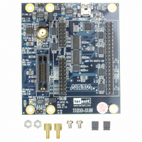
This chapter describes the architecture of the THDB-SUM board including its PCB and block diagram. 2.1 The picture of the TDRB-SUM board is shown in Figure 2.1 and Figure 2.2. It depicts the layout of the board and indicates ...
Page 6
SD Card Socket (J7) Figure 2.2. The THDB-SUM Back side – HSMC connector view The following components are provided on the THDB-SUM board : HSMC expansion connector (J1) Santa Cruz Headers(J3,J4,J5) Mictor connector (J2) SMA connector (J6) Hi-Speed USB On-The-Go ...
Page 7
Figure 2.3 shows the block diagram of the THDB-SUM board Connector Figure 2.3. The block diagram of the THDB-SUM board 2.2 Block Diagram HSMC SD Card Interface Mictor Connector Interface External Clock Input I2C Interface SC Interface USB Interface ...
Page 8
This section will describe the detailed information of the components, connector interfaces, and the pin mapping tables of the THDB-SUM board This section describes the HSMC connector on the THDB-SUM board THDB-SUM board contains an Altera standard HSMC connector. All ...
Page 9
HSMC_SCL 34 HSMC_TMS 36 HSMC_TDI 38 SD Wpn ...
Page 10
SD DAT3 42 SD DAT2 44 46 HSPROTO_RESET 48 HSPROTO_IO0 50 52 HSPROTO_IO1 54 HSPROTO_IO2 56 58 HSPROTO_IO3 60 HSPROTO_IO4 62 64 HSPROTO_IO5 66 HSPROTO_IO6 68 70 HSPROTO_IO7 72 HSPROTO_IO8 74 76 HSPROTO_IO9 78 HSPROTO_IO10 80 82 HSPROTO_IO11 84 HSPROTO_IO12 ...
Page 11
MICTOR_D14 102 MICTOR_D15 104 12V 106 MICTOR_D16 108 MICTOR_D17 110 12V 112 MICTOR_D18 114 MICTOR_D19 116 12V 118 MICTOR_D20 120 MICTOR_D21 122 12V 124 MICTOR_D22 126 MICTOR_D23 128 12V 130 MICTOR_D24 132 HSPROTO_IO23 134 12V 136 HSPROTO_IO24 138 HSPROTO_IO25 140 ...
Page 12
This section describes the Santa Cruz connector on the THDB-SUM board The THDB-SUM board comes with Santa Cruz connectors (J3, J4 and J5) to connect to a daughter board with Santa Cruz interface. On the THDB-SUM, the pin of SC ...
Page 13
HSMC Connector (J1) HSPROTO_RESET HSPROTO_CARDSEL HSPROTO_IO[40..0] Figure 3.6 The diagram of the logic level transform block Table 3.2 The configuration of the logic level on the HSPROTO_IO BUS JP3 setting Open Close Table 3.3 The configuration of the logic level ...
Page 14
Figure 3.7 Santa Cruz connector pin-outs Table 3.4 The pin assignments of the Santa Cruz connector J3 SC Pin Number SC Signal Name 3 PROTO_IO40 4 PROTO_IO29 5 PROTO_IO30 6 PROTO_IO31 7 PROTO_IO32 8 PROTO_IO33 9 PROTO_IO34 10 PROTO_IO35 11 ...
Page 15
Table 3.6 The pin assignments of the Santa Cruz connector J5 SC Pin Number SC Signal Name 1 PROTO_RESET 3 PROTO_IO0 4 PROTO_IO1 5 PROTO_IO2 6 PROTO_IO3 7 PROTO_IO4 8 PROTO_IO5 9 PROTO_IO6 10 PROTO_IO7 11 PROTO_IO8 12 PROTO_IO9 13 ...
Page 16
This section describes the USB On-The-Go transceiver on the THDB-SUM board The THDB-SUM is equipped with a NXP ISP1504C USB On-The-Go transceiver (U11) and Mini USB AB type receptacle connector (J8) to provide USB interface to the HSMC interface ...
Page 17
HSMC Connector (J1) Bus HSPROTO_IO Switch (U1,U2) JP1 Open Figure 3.8 The block diagram of the USB OTG transceiver and HSMC connector Table 3.8 The pin assignments of the USB OTG Transceiver U11 USB Pin USB Signal Name Number 1 ...
Page 18
This section describes how to use the Mictor connector on the THDB-SUM board The Mictor connector (J2) can be used for logic analysis on the HSMC-interfaced host board by connecting an external scope or a logic analyzer to it. the ...
Page 19
MICTOR_D7 25 MICTOR_D20 26 MICTOR_D6 27 MICTOR_D19 28 MICTOR_D5 29 MICTOR_D18 30 MICTOR_D4 31 MICTOR_D17 32 MICTOR_D3 33 MICTOR_D16 34 MICTOR_D2 35 MICTOR_D15 36 MICTOR_D1 37 MICTOR_D14 38 MICTOR_D0 11 MICTOR_TDO 15 MICTOR_TCK 17 MICTOR_TMS 19 MICTOR_TDI To use ...
Page 20
Short TDI and TDO pin of the J4 J4 Figure 3.10 The configuration of the Cyclone III start board for controlling the JTAG chain using the Mictor THDB-SUM Board Mictor connector J2 MICOTR_TDI MICOTR_TDI MICOTR_TDO MICOTR_TDO Figure 3.11 The JTAG ...
Page 21
HSMC Connector SD_DAT2 SD_DAT3 SD_CMD SD_CLK SD_DAT0 SD_DAT1 SD_WPn Figure 3.12 The block diagram of the SD Card socket and HSMC connector Table 3.10 The pin assignments of the SD Card Socket SD Card Socket Pin Number Signal Name 1 ...
Page 22
This section describes the I2C Serial EEPROM on the THDB-SUM board The THDB-SUM board provides an EEPROM (U10) which can be configured by the I2C interface. The size of the EEPROM is 128 bit that can store the board information ...
Page 23
This section describes the power supply on the THDB-SUM board The power distribution on the THDB-SUM board is shown in 12V HSMC Connector (J1) VCC33 Figure 3.14. THDB-SUM board power distribution diagram. 3.8 Power Supply Figure VCC50 REG3 VSC REG2 ...
Page 24
This chapter illustrates how to connect the THDB-SUM board to a HSMC interface host board using a Cyclone III Starter Board as an example 4.1 Connecting THDB-SUM Board to Cyclone III Start Board This section describes how to use THD-SUM ...
Page 25
R3) and HSMC_CLKIN_p2/n2 (form a close loop via R4). Therefore, using any one of the signal in a LVDS pair under single-ended mode will prevent users from using the other signal in the same pair. ...
Page 26
Date SEP 3, 2008 MAR 13,2009 DEC 2, 2009 5.2 Always Visit THDB-SUM Webpage for New Main board We will be continuing providing interesting examples and labs on our THDB-SUM webpage. Please visit www.altera.com or SUM.terasic.com for more information. 5.1 ...