P0001 Terasic Technologies Inc, P0001 Datasheet - Page 21
P0001
Manufacturer Part Number
P0001
Description
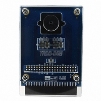
MODULE DIGITAL CAMERA 5MP (D5M)
Manufacturer
Terasic Technologies Inc
Datasheet
1.P0001.pdf
(24 pages)
Specifications of P0001
Accessory Type
Digital Camera
For Use With/related Products
DE2, DE1, TREX_C1
Lead Free Status / RoHS Status
Lead free / RoHS Compliant
Other names
TRDB_D5M
Available stocks
Company
Part Number
Manufacturer
Quantity
Price
Company:

Part Number:
P0001
Manufacturer:
Terasic Technologies Inc
Quantity:
135


3.6
Configuring the Camera (DE1 Board Users)
Locate the project directory from the CD-ROM included and follow the steps
below:
Directory: Demonstration / DE1_CAMERA
FPGA Bitstream Used: DE1_D5M.sof or DE1_D5M.pof
1.
2.
3.
4.
5.
6.
7.
8.
9.
Ensure the connection is set correctly as shown in Figure 3.7. Make sure
the D5M is connected to JP2 (GPIO 1) of the DE1 board.
Download the bitstream (DE1_D5M.sof/pof) to the DE1 board.
Connect the VGA output of the DE1 board to a VGA monitor.
Press KEY0 on the DE1 board to reset the circuit.
You can press KEY3 to switch to the FREE RUN mode and you should be
able to see whatever the camera sees on the VGA display.
Press KEY2 to take a shot of the photo; you can press KEY3 again to switch
back to FREE RUN mode.
Users can use the SW[0] with KEY1 to set the exposure time for brightness
adjustment of the image captured. When SW[0] is set to Off, the brightness
of image will be increased as KEY1 is pressed longer. If SW[0] is set to On,
the brightness of image will be decreased as KEY1 is pressed shorter.
Set the SW[8] to On (upper position), the captured image will be enlarged
with KEY0 and KEY3 pressed in order.
Table 3.5 summarizes the functional keys of the digital camera.
Figure 3.7. The Connection Setup for DE1 users
19
Digital Camera Design Demonstration
Related parts for P0001
Image
Part Number
Description
Manufacturer
Datasheet
Request
R

Part Number:
Description:
DE2-70 CALL FOR ACADEMIC PRICING
Manufacturer:
Terasic Technologies Inc
Datasheet:

Part Number:
Description:
USB BLASTER CABLE
Manufacturer:
Terasic Technologies Inc
Datasheet:

Part Number:
Description:
BOARD ADAPTER HSMC TO GPIO
Manufacturer:
Terasic Technologies Inc
Datasheet:

Part Number:
Description:
BOARD ADAPTER THDB-SUM
Manufacturer:
Terasic Technologies Inc
Datasheet:

Part Number:
Description:
KIT DEV 4.3" LCD TOUCH PANEL
Manufacturer:
Terasic Technologies Inc
Datasheet:

Part Number:
Description:
DAUGHTER BOARD AD/DA GPIO ADA
Manufacturer:
Terasic Technologies Inc

Part Number:
Description:
DAUGHTER BOARD AD/DA HSMC ADA
Manufacturer:
Terasic Technologies Inc

Part Number:
Description:
KIT MAX II MICRO
Manufacturer:
Terasic Technologies Inc
Datasheet:

Part Number:
Description:
BOARD DEV/EDUCATION ALTERA DE0
Manufacturer:
Terasic Technologies Inc
Datasheet:

Part Number:
Description:
BOARD DEV DE1 ALTERA
Manufacturer:
Terasic Technologies Inc
Datasheet:

Part Number:
Description:
DE2 CALL FOR ACADEMIC PRICING
Manufacturer:
Terasic Technologies Inc

Part Number:
Description:
MODULE DIGITAL CAMERA 1.3MP
Manufacturer:
Terasic Technologies Inc
Datasheet:

Part Number:
Description:
SENSOR CMOS 1.3MEGA (FOR P0349)
Manufacturer:
Terasic Technologies Inc
Datasheet:

Part Number:
Description:
KIT DEV 3.6" DIGITAL PANEL
Manufacturer:
Terasic Technologies Inc
Datasheet: