PL-BYTEBLASTER2N Altera, PL-BYTEBLASTER2N Datasheet
PL-BYTEBLASTER2N
Specifications of PL-BYTEBLASTER2N
PL-BYTEBLASTER2
Available stocks


Related parts for PL-BYTEBLASTER2N


PL-BYTEBLASTER2N Summary of contents
Page 1
... Innovation Drive San Jose, CA 95134 www.altera.com ByteBlaster II Download Cable Software Version: Document Version: Document Date: User Guide 8.0 1.4 July 2008 ...
Page 2
... Altera warrants performance of its semiconductor products to current specifications in accordance with Altera's standard warranty, but reserves the right to make changes to any products and services at any time without notice. Altera assumes no responsibility or liability arising out of the application or use of any information, product, or service described herein except as expressly agreed to in writing by Altera Corporation ...
Page 3
... Cable-to-Board Connection . . . . . . . . . . . . . . . . . . . . . . . . . . . . . . . . . . . . . . . . . . . . . . . . . . . . . . . . . . . . . 2–2 ByteBlaster II 25-Pin Header Connection . . . . . . . . . . . . . . . . . . . . . . . . . . . . . . . . . . . . . . . . . . . . . . . . . 2–2 ByteBlaster II 10-Pin Header Connection . . . . . . . . . . . . . . . . . . . . . . . . . . . . . . . . . . . . . . . . . . . . . . . . . 2–3 Circuit Board Header Connection . . . . . . . . . . . . . . . . . . . . . . . . . . . . . . . . . . . . . . . . . . . . . . . . . . . . . . . 2–4 Operating Conditions . . . . . . . . . . . . . . . . . . . . . . . . . . . . . . . . . . . . . . . . . . . . . . . . . . . . . . . . . . . . . . . . . . . . 2–4 Statement of China-RoHS Compliance . . . . . . . . . . . . . . . . . . . . . . . . . . . . . . . . . . . . . . . . . . . . . . . . . . . . . 2–5 Chapter Info. Additional Information Referenced Documents . . . . . . . . . . . . . . . . . . . . . . . . . . . . . . . . . . . . . . . . . . . . . . . . . . . . . . . . . . . . . . . . Info–1 Revision History . . . . . . . . . . . . . . . . . . . . . . . . . . . . . . . . . . . . . . . . . . . . . . . . . . . . . . . . . . . . . . . . . . . . . Info–2 How to Contact Altera . . . . . . . . . . . . . . . . . . . . . . . . . . . . . . . . . . . . . . . . . . . . . . . . . . . . . . . . . . . . . . . . Info–3 Typographic Conventions . . . . . . . . . . . . . . . . . . . . . . . . . . . . . . . . . . . . . . . . . . . . . . . . . . . . . . . . . . . . . Info– ...
Page 4
... ByteBlaster II Download Cable User Guide © July 2008 Altera Corporation ...
Page 5
... List of Figures Figure 1–1: The ByteBlaster II Download Cable . . . . . . . . . . . . . . . . . . . . . . . . . . . . . . . . . . . . . . . . . . . . . . . . 1-2 Figure 1–2: Hardware Setup Dialog Box . . . . . . . . . . . . . . . . . . . . . . . . . . . . . . . . . . . . . . . . . . . . . . . . . . . . . . 1-6 Figure 2–1: ByteBlaster II Block Diagram . . . . . . . . . . . . . . . . . . . . . . . . . . . . . . . . . . . . . . . . . . . . . . . . . . . . . . 2-2 Figure 2–2: ByteBlaster II 10-Pin Female Plug Dimensions . . . . . . . . . . . . . . . . . . . . . . . . . . . . . . . . . . . . . . . 2-3 Figure 2–3: 10-Pin Male Header Dimensions . . . . . . . . . . . . . . . . . . . . . . . . . . . . . . . . . . . . . . . . . . . . . . . . . . . 2-4 © July 2008 Altera Corporation 3 ...
Page 6
... ByteBlaster II Download Cable User Guide List of Figures © July 2008 Altera Corporation ...
Page 7
... Table 2–1: ByteBlaster II VCC(TRGT) Pin Voltage Requirements . . . . . . . . . . . . . . . . . . . . . . . . . . . . . . . . . 2-1 Table 2–2: ByteBlaster II 25-Pin Header Pin-Outs . . . . . . . . . . . . . . . . . . . . . . . . . . . . . . . . . . . . . . . . . . . . . . . 2-2 Table 2–3: ByteBlaster II Female Plug Signal Names and Programming Modes . . . . . . . . . . . . . . . . . . . . . 2-3 Table 2–4: ByteBlaster II Cable Absolute Maximum Ratings . . . . . . . . . . . . . . . . . . . . . . . . . . . . . . . . . . . . . 2-4 Table 2–5: ByteBlaster II Cable Recommended Operating Conditions . . . . . . . . . . . . . . . . . . . . . . . . . . . . . 2-5 Table 2– ...
Page 8
... ByteBlaster II Download Cable User Guide List of Tables © July 2008 Altera Corporation ...
Page 9
... The ByteBlaster devices. This cable drives configuration data from a standard parallel printer port on your PC to the device on the PCB. Because design changes are downloaded directly to the device, prototyping is easy and you can accomplish multiple design iterations in quick succession. Supported Devices You can use the ByteBlaster II download cable to download configuration data to the following Altera devices: ® ...
Page 10
... This section describes how to install and set up the ByteBlaster II download cable for device configuration and programming. 1 For plug and header dimensions, pin names, and operating conditions, refer to Chapter 2, ByteBlaster II Specifications download cable to the circuit board as instructed below: 1. Disconnect the power cable from the circuit board. ...
Page 11
... Select win2000.inf and click Open to continue. 10. Click OK to install the selected driver. 11. Click Continue Anyway when the Software Installation warning appears. 12. Select Altera ByteBlaster and click Next to continue. 13. Click Next to install the driver. © July 2008 Altera Corporation or “Installing the Driver on a Linux ByteBlaster II Download Cable User Guide 1– ...
Page 12
... To verify that an RPM is installed, use the rpm -q <name> command. For example, rpm -q gcc verifies that the gcc RPM is installed. 1 You do not need to install the ByteBlaster II download cable before installing the Altera ByteBlaster kernel driver. ...
Page 13
... To determine whether the ByteBlaster II download cable and the Altera ByteBlaster kernel driver are installed correctly, display a list of available devices by typing the following command at the command prompt: jtagconfig r You should see a list of devices on your JTAG chain, including the ByteBlaster II download cable ...
Page 14
... Serial Programming, and Active Serial modes. Table 1–1. Programming Modes Mode Joint Test Action Group (JTAG) Programs or configures all Altera devices supported by the Quartus II software, excluding FLEX 6000 and EPCS serial configuration devices. In-Socket Programming Not supported by the ByteBlaster II cable. Passive Serial Programming Configures all Altera devices supported by the Quartus II software, excluding MAX 3000, MAX 7000, MAX II, and EPCS serial configuration devices ...
Page 15
... Chapter 1: Setting Up the ByteBlaster II Download Cable Software Setup ■ Overview: Converting Programming Files © July 2008 Altera Corporation 1–7 ByteBlaster II Download Cable User Guide ...
Page 16
... ByteBlaster II Download Cable User Guide Chapter 1: Setting Up the ByteBlaster II Download Cable Software Setup © July 2008 Altera Corporation ...
Page 17
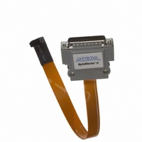
... Operating conditions ByteBlaster II Connections The ByteBlaster II cable has a 25-pin male header parallel printer plug that connects to the PC, and a 10-pin female plug that connects to the circuit board. Data is downloaded from the parallel printer port on the PC through the ByteBlaster II cable to the circuit board. ...
Page 18
... CC(TRGT) EPC4, EPC8, and EPC16 devices EPCS1, EPCS4, EPCS16, EPCS64, and EPCS128 devices Cable-to-Board Connection The ByteBlaster II cable has a standard parallel printer plug that connects to the PC. Figure 2–1 shows a block diagram of the ByteBlaster II download cable. Figure 2–1. ByteBlaster II Block Diagram V CC ...
Page 19
... Detect Signal ground GND ByteBlaster II 10-Pin Header Connection The 10-pin female plug connects to a 10-pin male header on the circuit board. Figure 2–2 shows the dimensions of the female plug. Figure 2–2. ByteBlaster II 10-Pin Female Plug Dimensions Table 2–3 identifies the 10-pin female plug signal names and the corresponding programming mode. Table 2– ...
Page 20
... Signal ground GND 1 The circuit board must supply VCC(TRGT) and ground to the ByteBlaster II cable for the I/O drivers. Circuit Board Header Connection The circuit board’s 10-pin male header has two rows of five pins connected to the device’s programming or configuration pins. ...
Page 21
... Target supply voltage, 5.0-V operation CC(TRGT) Target supply voltage, 3.3-V operation Target supply voltage, 2.5-V operation Target supply voltage, 1.8-V operation Target supply voltage, 1.5-V operation Note to Table 2–5: (1) The operating conditions are identical for both leaded and lead-free ByteBlaster II download cables. ...
Page 22
... SJ/T11363-2006 standard. ByteBlaster II Download Cable User Guide (Note 1) Hexavalent Chromium (Cr6+) Mercury (Hg Chapter 2: ByteBlaster II Specifications Statement of China-RoHS Compliance Polybrominated Polybrominated diphenyl Ethers biphenyls (PBB) (PBDE © July 2008 Altera Corporation ...
Page 23
... Configuration scheme (general description) ■ Programming files (general description) ■ ■ Refer to the following procedures in Quartus II Help: Programming a Single Device or Multiple Devices in JTAG or Passive Serial ■ Mode Programming a Single Device in Active Serial Programming Mode ■ Selecting the Communications Cable for the SignalTap II Logic Analyzer ■ ...
Page 24
... January 2008 Updated “Supported Devices” v1.2 Updated Table 1–1. Updated Table 2–1. Added new note to Added note about RoHS compliance. Updated “Revision History” December 2004 Re-release v1.1 July 2004 Initial release v1.0 ByteBlaster II Download Cable User Guide Changes Made page “ ...
Page 25
... Signal and port names are shown in lowercase Courier type. Examples: Courier type input. Anything that must be typed exactly as it displays is shown in Courier type. For example: c:\qdesigns\tutorial\chiptrip.gdf Report File, references to parts of files (for example, the AHDL keyword well as logic function names (e.g., 1 ...
Page 26
... A warning calls attention to a condition or possible situation that can cause injury to the user. r The angled arrow indicates you should press the Enter key. f The feet direct you to more information about a particular topic. ByteBlaster II Download Cable User Guide (Part Meaning Typographic Conventions © July 2008 Altera Corporation ...