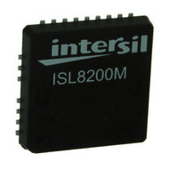
ISL8200MIRZ Intersil, ISL8200MIRZ Datasheet - Page 14

ISL8200MIRZ
Manufacturer Part Number
ISL8200MIRZ
Description
IC BUCK SYNC ADJ 10A 23-QFN
Manufacturer
Intersil
Type
Point of Load (POL) Non-Isolatedr
Datasheet
1.ISL8200MIRZ.pdf
(23 pages)
Specifications of ISL8200MIRZ
Output
0.6 ~ 6V
Number Of Outputs
1
Power (watts)
60W
Mounting Type
Surface Mount
Voltage - Input
3 ~ 20V
Package / Case
23-QFN
1st Output
0.6 ~ 6 VDC @ 10A
Size / Dimension
0.59" L x 0.59" W x 0.09" H (15mm x 15mm x 2.2mm)
Power (watts) - Rated
60W
Operating Temperature
-40°C ~ 85°C
Current - Output
10A
Voltage - Output
0.6 ~ 6 V
Frequency - Switching
700kHz ~ 1.5MHz
Synchronous Rectifier
Yes
Rohs Compliant
Yes
Lead Free Status / RoHS Status
Lead free / RoHS Compliant
3rd Output
-
2nd Output
-
Available stocks
Company
Part Number
Manufacturer
Quantity
Price
Part Number:
ISL8200MIRZ
Manufacturer:
INTERSIL
Quantity:
20 000
The output voltage accuracy can be improved by
maintaining the impedance at V
V
impedance between V
The module has minimum input voltage at a given output
voltage, which needs to be a minimum of 1.43 times
output voltage if operating at F
frequency. This is due to the Minimum PWM OFF Time
(t
The equation to determine the minimum V
the required V
t
for the 700kHz switching frequency = 1428ns
Selection of the Input Capacitor
The input filter capacitor should be based on how much
ripple the supply can tolerate on the DC input line. The
larger the capacitor, the less ripple expected, but
consideration should be taken for the higher surge
current during power-up. The ISL8200M provides the
soft-start function that controls and limits the current
surge. The value of the input capacitor can be calculated
by Equation 4:
Where:
C
I
Δt is the turn on time of the high-side switch (µs)
ΔV is the allowable peak-to-peak voltage (V)
In addition to the bulk capacitance, some low Equivalent
Series Inductance (ESL) ceramic capacitance is
recommended to decouple between the drain terminal of
the high side MOSFET and the source terminal of the low
side MOSFET. This is used to reduce the voltage ringing
created by the switching current across parasitic circuit
elements.
Output Capacitors
The ISL8200M is designed for low output voltage ripple.
The output voltage ripple and transient requirements can
be met with bulk output capacitors (C
enough Equivalent Series Resistance (ESR). C
a low ESR tantalum capacitor, a low ESR polymer
capacitor or a ceramic capacitor. The typical capacitance
is 330µF and decoupled ceramic output capacitors are
used per phase. The internally optimized loop
compensation provides sufficient stability margins for all
ceramic capacitor applications with a recommended total
value of 300µF per phase. Additional output filtering may
V
V
C
SW
IN
IN_MIN
IN_MIN
SEN1+
IN
IN
MIN-OFF
is the input current (A)
=
is the input capacitance (µF)
= switching period = 1/F
I
------------------ -
IN
) at or below 1kΩ effective impedance. Note: the
ΔV
=
=
×
).
1.43
------------------------------------------
t
Δt
SW
V
OUT
–
×
OUT
t
V
MIN_OFF
OUT
×
t
SW
is given by Equations 2 and 3:
SEN1+
14
and V
SW
SW
OUTSET
= 700kHz switching
SEN1-
OUT
(internal
is about 500kΩ.
) with low
IN
to support
OUT
can be
(EQ. 2)
(EQ. 3)
(EQ. 4)
ISL8200M
be needed if further reduction of output ripple or dynamic
transient spike is required.
Functional Description
Initialization
The ISL8200M requires V
single supply. Power-On Reset (POR) circuits
continually monitor the bias voltages (PVCC and V
and the voltage at EN pin. The POR function initiates
soft-start operation 384 clock cycles after the EN pin
voltage is pulled to be above 0.8V, all input supplies
exceed their POR thresholds and the PLL locking time
expires. The enable pin can be used as a voltage
monitor and to set desired hysteresis with an internal
30µA sinking current going through an external
resistor divider. The sinking current is disengaged after
the system is enabled. This feature is especially
designed for applications that require higher input rail
POR for better undervoltage protection. For example,
in 12V applications, R
will set the turn-on threshold (V
turn-off threshold (V
hysteresis (V
During shutdown or fault conditions, the soft-start is
quickly reset while UGATE and LGATE immediately
change state (<100ns) upon the input dropping below
POR.
Voltage Feedforward
The voltage applied to the FF pin is fed to adjust the
sawtooth amplitude of the channel. The amplitude the
sawtooth is set to 1.25 times the corresponding FF
voltage when the module is enabled. This configuration
helps to maintain a constant gain
(
optimum loop response over a wide input voltage range.
The sawtooth ramp offset voltage is 1V (equal to
0.8V*1.25), and the peak of the sawtooth is limited to
V
peak-to-peak amplitude of V
the feed-forward voltage effective range is typically 3x as
the ramp amplitude ranges from 1V to 3V.
A 384 cycle delay is added after the system reaches its
rising POR and prior to the soft-start. The RC timing at
the FF pin should be sufficiently small to ensure that the
input bus reaches its static state and the internal ramp
circuitry stabilizes before soft-start. A large RC could
cause the internal ramp amplitude not to synchronize
with the input bus voltage during output start-up or
G
CC
M
PLL LOCKING
FIGURE 21. SOFT-START INITIALIZATION LOGIC
- 1.4V. With V
=
PVCC POR
VCC POR
V
EN POR
IN
HIGH = ABOVE POR; LOW = BELOW POR
⋅
D
MAX
EN_HYS
⁄
ΔV
CC
RAMP
).
EN_FTH
= 5.4V, the ramp has a maximum
UP
AND
CC
) and input voltage to achieve
= 53.6k and R
and PVCC to be biased by a
CC
) to 9V, with 1.6V
- 2.4V (equal to 3V); so
EN_RTH
CYCLES
384
DOWN
) to 10.6V and
SOFT-START
OF MODULE
February 26, 2010
= 5.23k
FN6727.1
CC
)


