LMZ10503TZX-ADJ/NOPB National Semiconductor, LMZ10503TZX-ADJ/NOPB Datasheet - Page 10
LMZ10503TZX-ADJ/NOPB
Manufacturer Part Number
LMZ10503TZX-ADJ/NOPB
Description
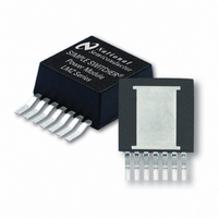
IC BUCK SYNC ADJ 3A TO-PMOD-7
Manufacturer
National Semiconductor
Series
SIMPLE SWITCHER®r
Type
Point of Load (POL) Non-Isolated with UVLOr
Datasheet
1.LMZ10503TZX-ADJNOPB.pdf
(22 pages)
Specifications of LMZ10503TZX-ADJ/NOPB
Output
0.8 ~ 5 V
Number Of Outputs
1
Power (watts)
15W
Mounting Type
Surface Mount
Voltage - Input
2.95 ~ 5.5 V
Package / Case
TO-PMOD-7, Power Module
1st Output
0.8 ~ 5 VDC @ 3A
Size / Dimension
0.40" L x 0.54" W x 0.18" H (10.16mm x 13.77mm x 4.57mm)
Power (watts) - Rated
15W
Operating Temperature
-40°C ~ 125°C
Efficiency
96%
Approvals
EN
Lead Free Status / RoHS Status
Lead free / RoHS Compliant
3rd Output
-
2nd Output
-
Other names
LMZ10503TZX-ADJ


www.national.com
A second criteria before finalizing the C
the RMS current capability. The necessary RMS current rat-
ing of the input capacitor to a buck regulator can be estimated
by
With this high AC current present in the input capacitor, the
RMS current rating becomes an important parameter. The
maximum input capacitor ripple voltage and RMS current oc-
cur at 50% duty cycle. Select an input capacitor rated for at
least the maximum calculated I
Additional bulk capacitance with higher ESR may be required
to damp any resonance effects of the input capacitance and
parasitic inductance.
Output Capacitor Selection
In general, 22 µF to 100 µF high quality dielectric (X5R, X7R)
ceramic capacitor rated at twice the maximum output voltage
is sufficient given the optimal high frequency characteristics
and low ESR of ceramic dielectrics. Although, the output ca-
pacitor can also be of electrolytic chemistry for increased
capacitance density.
Two output capacitance equations are required to determine
the minimum output capacitance. One equation determines
the output capacitance (C
The second equation determines C
sient characteristics. Select the largest capacitance value of
the two.
The minimum capacitance, given the maximum output volt-
age ripple (ΔV
ing equation:
Where the peak to peak inductor current ripple (Δi
to:
OUT
) requirement, is determined by the follow-
O
) based on PWM ripple voltage.
Cin(RMS)
O
based on the load tran-
.
in
bypass capacitor is
L
) is equal
10
R
value of the internal power inductor, where L = 2.2 µH, and
f
The minimum output capacitance requirement due to the
PWM ripple voltage is:
Three miliohms is a typical R
The following equation provides a good first pass capacitance
requirement for a load transient:
Where I
I
ΔV
±20 mV.
Therefore the capacitance requirement for the given design
parameters is:
In this particular design the output capacitance is determined
by the load transient requirements.
Table 1
pacitors that can be used with the LMZ10503.
SW
step
ESR
o_tran
= 1 MHz. Therefore, per the design example:
= 10% to 90% of the maximum load), V
is the total output capacitor ESR, L is the inductance
step
is the maximum output voltage deviation, which is
lists some examples of commercially available ca-
is the peak to peak load step (for this example
ESR
value for ceramic capacitors.
FB
= 0.8V, and
Related parts for LMZ10503TZX-ADJ/NOPB
Image
Part Number
Description
Manufacturer
Datasheet
Request
R

Part Number:
Description:
National Semiconductor [8-Bit D/A Converter]
Manufacturer:
National Semiconductor
Datasheet:
Part Number:
Description:
National Semiconductor [Media Coprocessor]
Manufacturer:
National Semiconductor
Datasheet:
Part Number:
Description:
Digitally Controlled Tone and Volume Circuit with Stereo Audio Power Amplifier, Microphone Preamp Stage and National 3D Sound
Manufacturer:
National Semiconductor
Datasheet:
Part Number:
Description:
Digitally Controlled Tone and Volume Circuit with Stereo Audio Power Amplifier, Microphone Preamp Stage and National 3D Sound
Manufacturer:
National Semiconductor
Datasheet:
Part Number:
Description:
AC97 Rev 2 Codec with Sample Rate Conversion and National 3D Sound
Manufacturer:
National Semiconductor
Part Number:
Description:
Manufacturer:
National Semiconductor
Datasheet:
Part Number:
Description:
Manufacturer:
National Semiconductor
Datasheet:
Part Number:
Description:
General Purpose, Low Voltage, Low Power, Rail-to-Rail Output Operational Amplifiers
Manufacturer:
National Semiconductor
Datasheet:
Part Number:
Description:
8-bit 20 MSPS flash A/D converter.
Manufacturer:
National Semiconductor
Datasheet:
Part Number:
Description:
Low Noise Quad Operational Amplifier
Manufacturer:
National Semiconductor
Datasheet:
Part Number:
Description:
Quad Differential Line Receivers
Manufacturer:
National Semiconductor
Datasheet:
Part Number:
Description:
Quad High Speed Trapezoidal? Bus Transceiver
Manufacturer:
National Semiconductor
Datasheet:
Part Number:
Description:
Dual Line Receiver
Manufacturer:
National Semiconductor
Datasheet:
Part Number:
Description:
TTL to 10k ECL Level Translator with Latch
Manufacturer:
National Semiconductor
Datasheet: