GS-R12FV0001.9 STMicroelectronics, GS-R12FV0001.9 Datasheet - Page 6
GS-R12FV0001.9
Manufacturer Part Number
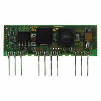
GS-R12FV0001.9
Description
CONVERTR MODULE DC-DC 1.9A 15SIP
Manufacturer
STMicroelectronics
Series
GS-R12FPr
Type
Point of Load (POL) Non-Isolatedr
Specifications of GS-R12FV0001.9
Output
1.235 ~ 5.5V
Number Of Outputs
1
Power (watts)
10W
Mounting Type
Through Hole
Voltage - Input
4.5 ~ 15V
Package / Case
10-SIP Module
1st Output
1.235 ~ 5.5 VDC @ 1.9A
Size / Dimension
1.52" L x 0.18" W x 0.50" H (38.7mm x 4.5mm x 12.7mm)
Power (watts) - Rated
10.5W
Operating Temperature
-25°C ~ 85°C
Efficiency
83%
Output Voltage
1.235 V to 5.5 V
Mounting Style
Through Hole
Lead Free Status / RoHS Status
Lead free / RoHS Compliant
3rd Output
-
2nd Output
-
Lead Free Status / Rohs Status
Lead free / RoHS Compliant
Other names
497-8253


Application information
4
4.1
4.2
4.3
4.4
4.5
6/13
Input voltage
Reference voltage
Inhibit function
Current limitation
Application information
The recommended maximum operating DC Input Voltage is 15 V including ripple voltage.
No capacitor is required for stability.
The inhibit feature allows to put the device in stand-by mode.
With INH pin 1 is higher than 2.2 V the device is disabled and the current consumption is
reduced to less than 100 µA for V
With INH pin lower than 0.8 V, the device is enabled.
If the INH pin is left floating, an internal pull up ensures that the voltage at the pin reaches
the inhibit threshold and the device is disabled.
The pin can be pulled to V
Multiple units synchronization
Using more than one unit on the same circuit, it is possible to synchronize the switching
frequency, connecting all pin 12 together (see
The unit with higher frequency becomes the master.
The device has two current limit protections, pulse by pulse and frequency fold back.
The current is sensed through a resistor and if it reaches the threshold, the on time is
reduced and consequently the output voltage, too.
Since the minimum switch ON time (necessary to avoid false overcurrent signal) is not
enough to obtain a sufficiently low duty cycle at 250 Hz, the output current could increase
again, in strong overcurrent or short circuit conditions.
For this reason the switching frequency is also reduced to keep the inductor current within
its maximum threshold limit.
The frequency depends on the feedback voltage.
As the feedback voltage decreases (due to the reduced duty cycle), the switching frequency
decrease too.
i
to disable the device.
i
= 15 V.
Figure
5).
GS-R12F
Related parts for GS-R12FV0001.9
Image
Part Number
Description
Manufacturer
Datasheet
Request
R

Part Number:
Description:
STMicroelectronics [RIPPLE-CARRY BINARY COUNTER/DIVIDERS]
Manufacturer:
STMicroelectronics
Datasheet:
Part Number:
Description:
STMicroelectronics [LIQUID-CRYSTAL DISPLAY DRIVERS]
Manufacturer:
STMicroelectronics
Datasheet:

Part Number:
Description:
BOARD EVAL FOR MEMS SENSORS
Manufacturer:
STMicroelectronics
Datasheet:
Part Number:
Description:
NPN TRANSISTOR POWER MODULE
Manufacturer:
STMicroelectronics
Datasheet:
Part Number:
Description:
TURBOSWITCH ULTRA-FAST HIGH VOLTAGE DIODE
Manufacturer:
STMicroelectronics
Datasheet:
Part Number:
Description:
Manufacturer:
STMicroelectronics
Datasheet:
Part Number:
Description:
DIODE / SCR MODULE
Manufacturer:
STMicroelectronics
Datasheet:
Part Number:
Description:
DIODE / SCR MODULE
Manufacturer:
STMicroelectronics
Datasheet:
Part Number:
Description:
Search -----> STE16N100
Manufacturer:
STMicroelectronics
Datasheet:
Part Number:
Description:
Search ---> STE53NA50
Manufacturer:
STMicroelectronics
Datasheet:
Part Number:
Description:
NPN Transistor Power Module
Manufacturer:
STMicroelectronics
Datasheet:
Part Number:
Description:
DIODE / SCR MODULE
Manufacturer:
STMicroelectronics
Datasheet: