BP5222A Rohm Semiconductor, BP5222A Datasheet
BP5222A
Specifications of BP5222A


Related parts for BP5222A


BP5222A Summary of contents
Page 1
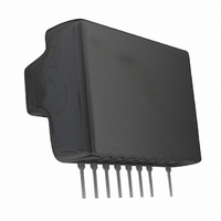
... Step-down DC/DC Converters(Non-isolated) BP5220A / BP5221A / BP5222A Description The BP5220A, BP5221A, BP5222A, are converters that use a pulse width modulation (PWM) system. They contain control circuits, switching devices, rectifiers, and coils, and operate by only connecting smoothing capacitor. With a high efficiency of power conversion, the modules are available in stand-alone 9-pin SIP packages with no heat sink required ...
Page 2
... BP5220A/BP5221A/BP5222A Block diagram BP5220A / BP5221A / BP5222A POWER SUPPLY CIRCUIT 9 Vi Electrical characteristics BP5220A (Unless otherwise noted : Vi=15V, Io=0.5A, SW=1, Ta=25˚C) Parameter Symbol Input voltage Vi Output voltage V Output current Line regulation Load regulation Output ripple voltage Power conversion efficiency f Switching frequency ...
Page 3
... ROHM Co., Ltd. All rights reserved. Min. Typ. Max. Unit 11 190 kHz SW 4.7 ON 200 OFF BP5220A / BP5221A / BP5222A Frequency counter Fig.1 T 3/7 Data Sheet Conditions Vi=15V to 38V Io=0.05A to 0.5A Io=0.5A Vo>11.2V Vo<0.1V, SW=2 Output Switching frequency=1/T Output ripple voltage 2010.03 - Rev. B ...
Page 4
... Be sure to use fuse for safety 120pF BP5220A / BP5221A / BP5222A 100 OFF 100k 2SC1740 Fig.6 4/7 Data Sheet BP5220A / BP5221A / BP5222A Fig.2 BP5220A / BP5221A / BP5222A Output OFF Fig 24V 0.2 0.4 0.6 0.8 1.0 1.2 OUTPUT CURRENT (A) Fig 470 F 2010.03 - Rev. B ...
Page 5
... ROHM Co., Ltd. All rights reserved. (2) When increasing the output voltage 100 F VR BP5220A / BP5221A / BP5222A sure to use 470 F 100 F fuse for safety. 470k 2SC1740R + Fig.9 5/7 Data Sheet BP5220A / BP5221A / BP5222A sure to use VR 470 F fuse for safety. Fig 2010.03 - Rev ...
Page 6
... BP5220A/BP5221A/BP5222A Operation notes (1) No circuit is installed in the modules to protect against excessive output currents. Therefore, take physical safety measures such as using a fuse if short-circuit loading is probable. (2) The output current should be reduced according to an increase in the input voltage or ambient temperature. Use the modules within the derating curve range. ...
Page 7
... ROHM Co., Ltd. All rights reserved. 100 Vi=23V 80 Vi=38V Vi=30V 120 0 0.1 0.2 0.3 0.4 0.5 OUTPUT CURRENT : I (A) O Fig.17 Efficiency BP5220A / BP5221A / BP5222A Voltage difference between pins 2 and 9 Fig.19 ASO measurement circuit 7/7 Data Sheet 10 Pw=1ms 4.5A 2.2A Pw=10ms 1 Tc=25 ° ...
Page 8
...
Page 9
No copying or reproduction of this document, in part or in whole, is permitted without the consent of ROHM Co.,Ltd. The content specified herein is subject to change for improvement without notice. The content specified herein is for the purpose ...