VPOL15A-5-SIP CUI Inc, VPOL15A-5-SIP Datasheet
VPOL15A-5-SIP
Specifications of VPOL15A-5-SIP


Related parts for VPOL15A-5-SIP


VPOL15A-5-SIP Summary of contents
Page 1
... Power De-Rating Curves 7.5 Efficiency vs Load Curves 7.6 Input Capacitance at the Power Module 7.7 Test Set-Up 7.8 Remote Sense Compensation 7.9 VPOL15A-5-SIP Series Output Voltage Adustment. 7.10 Output Ripple and Noise Measurement 7.11 Output Capacitance 8. MECHANICAL OUTLINE DIAGRAMS 8.1 VPOL15A-5-SIP Mechanical Outline Diagrams phone 503 ...
Page 2
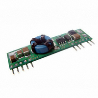
... Figure 1. Extremely high efficiency power conversion is achieved through the use of synchronous rectification and drive techniques. Essentially, the powerful VPOL15A-5-SIP series topology is based on a non-isolated synchronous buck converter. The control loop is optimized for unconditional stability, fast transient response and a very tight line and load regulation ...
Page 3
... PART NUMBER: VPOL15A-5-SIP 4. Technical Specifications (All specifications are typical at nominal input, full load at 25°C unless otherwise noted.) PARAMETER ABSOLUTE MAXIMUM RATINGS Input Voltage Continuous Operating Temp erature See Thermal Considerations Section Storage Temperature INPUT CHARACTERISTICS Operating Input Voltage Input Under-Voltage Lockout ...
Page 4
... PART NUMBER: VPOL15A-5-SIP PARAMETER DYNAMIC CHARACTERISTICS Output Voltage Transient Response Error Brand Setting Time (within 1% Vout nominal) EFFICIENCY 100% Load ISOLATION CHARACTERISTICS Input to Output FEATURE CHARACTERISTICS Switching Frequency On/Off Control, Positive Logic Remote On/Off Logic Low (Module Off) Logic High (Module On) ...
Page 5
... The remote on/off input feature to turn the converter on that can standard. The VPOL15A-5-SIP series converters are turned on if the remote on/off pin is high, or left open or floating. Setting the pin low will turn the converter ‘Off’. The signal level of the remote on/off input is defined with respect to ground. If not using the remote on/off pin, leave the pin open (module will be on). The part number suffix “ ...
Page 6
... Layout Design Challenges. In optimizing thermal design the PCB is utilized as a heat sink. Also some heat is transferred from the VPOL15A-5-SIP module to the main board through connecting pins. The system designer or the end user must ensure that other components and metal in the vicinity of the ...
Page 7
... The thermal data presented is based on measurements taken in a set-up as shown in Figure 6. Figures represent the test data. Note that the airflow is parallel to the long axis of the module as shown in Figure 6 for the VPOL15A-5-SIP. The temperature at either location should not exceed 110 °C. The output 76.2(3.0) power of the module should not exceed the rated power for the module (VO, set x IO, max) ...
Page 8
... PART NUMBER: VPOL15A-5-SIP TYPICAL POWER DERATING FOR 5 Vin 3.3 Vout SIP15-05S33A Derating Curve 0LFM 6 100LFM 4 200LFM Ambient Temperature( C) NOTE: 1. specific input & output derating curves available, please contact V-Infinity for detail th 20050 SW 112 Ave. Tualatin, Oregon 97062 DESCRIPTION: point of load converter ...
Page 9
... VPOL15A-5-SIP Vo=2.5V (Eff Vs Io Current Load (A) VPOL15A-5-SIP Vo=1.5V (Eff Vs Io Current Load (A) VPOL15A-5-SIP Vo=1.0V (Eff Vs Io Current Load ( 08/2007 3.0V 5.0V 5.5V 3.0V 5.0V 5.5V 3.0V 5.0V ...
Page 10
... PART NUMBER: VPOL15A-5-SIP 7.6 Input Capacitance at the Power Module The VPOL15A-5-SIP converters must be connected to a low AC source impedance void problems with loop stability source inductance should be low. Also, the input capacitors should be placed close to the converter input pins to de-couple distribution inductance. However, the external input capacitors are chosen for suitable ripple handling capability ...
Page 11
... PART NUMBER: VPOL15A-5-SIP 7.9 VPOL15A-5-SIP Series Output Voltage Adustment. The output voltage of the VPOL15A-5-SIP can be adjusted in the range 0.9V to 3.63V by connecting a single resistor on the motherboard (shown as Rtrim) in Figure 14. When trim resistor is not connected the output voltage defaults to 0.75V +Vin +Vo Trim VPOL15A-5-SIP ...
Page 12
... SW 112 Ave. Tualatin, Oregon 97062 DESCRIPTION: point of load converter 0.335(8.50)max. 0.23(5. 0.500(12.70) 0.28(7.1) 0.050(1.30) 0.025(0.64) Figure 16 VPOL15A-5-SIP Mechanical Outline Diagram phone 503.612.2300 fax 503.612.2382 rev. page 08/2007 date PIN CONNECTION Pin FUNCTION +Output 1 2 +Output 3 +Sense ...