TOTX141P(F,T) Toshiba, TOTX141P(F,T) Datasheet
TOTX141P(F,T)
Specifications of TOTX141P(F,T)


Related parts for TOTX141P(F,T)


TOTX141P(F,T) Summary of contents
Page 1
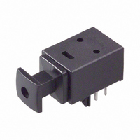
FIBER OPTIC TRANSMITTING MODULE FOR DIGITAL AUDIO INTERFACE l Conforms to JEITA Standard CP−1201 (For Digital Audio Interfaces including Fiber Optic inter−connections). l LED is driven by differential circuit. l Mini package type. 1. Maximum Ratings (Ta = 25°C) Characteristics ...
Page 2
Recommended Operating Conditions Characteristics Supply Voltage High−Level Input Voltage Low−Level Input Voltage 3. Electrical and Optical Characteristics Characteristics Data Rate Transmission Distance Pulse Width Distortion (Note 4) Fiber Output Power (Note 5) Center Emission Wavelength Current Consumption High Level ...
Page 3
Application Circuit 6. Required Optical Fiber with Fiber Optic Connectors □□ TOCP172− Board layout hole pattern (for reference) 3 TOTX141P Unit: mm Recommended PCB thickness: 1.6 mm 2001-08-16 ...
Page 4
... Note that it is not dust or waterproof. As mentioned before, optical modules are optical components. Thus, in principle, soldering where there may be flux residue and flux removal after soldering is not recommended. Toshiba recommend that soldering be performed without the optical module mounted on the board. Then, after the board has been cleaned, the optical module should be soldered on to the board manually. If the optical module cannot be soldered manually, use non− ...
Page 5
... It is the responsibility of the buyer, when utilizing Toshiba products, to observe standards of safety, and to avoid situations in which the malfunction or failure of a Toshiba product could cause loss of human life, bodily injury or damage to property. When developing equipment, please ensure that Toshiba products are used within the specified operating ranges set forth in the most recent product specifications ...
Page 6
... TOSHIBA is continually working to improve the quality and reliability of its products. Nevertheless, semiconductor devices in general can malfunction or fail due to their inherent electrical sensitivity and vulnerability to physical stress the responsibility of the buyer, when utilizing TOSHIBA products, to comply with the standards of safety in making a safe design for the entire system, and to avoid situations in which a malfunction or failure of such TOSHIBA products could cause loss of human life, bodily injury or damage to property ...