TOTX141P Toshiba, TOTX141P Datasheet
TOTX141P
Specifications of TOTX141P
Available stocks


Related parts for TOTX141P

TOTX141P Summary of contents
Page 1
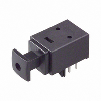
... Handling precaution: The LED’s used in this product contain GaAs (Gallium Arsenide). Care must be taken to protect the safety of people and the environment when scrapping or terminal processing. FIBER OPTIC TRANSMITTING MODULE TOTX141P Symbol Rating T − stg T − opr V −0 −0 0 260 (Note 1) sol 1 TOTX141P Unit: mm Unit °C ° °C 2001-08-16 ...
Page 2
... Note 2: LED is on when input signal is high, and off when it is low. The duty factor must be maintained between 25 to 75%. Note 3: All Plastic Fiber (970 / 1000 µm). Note 4: Between input of TOTX141P and output of fiber optic receiving module. Note 5: Measure with a standard optical fiber, peak value. 4. Mechanical Characteristics ...
Page 3
... Application Circuit 6. Required Optical Fiber with Fiber Optic Connectors □□ TOCP172− Board layout hole pattern (for reference) 3 TOTX141P Unit: mm Recommended PCB thickness: 1.6 mm 2001-08-16 ...
Page 4
... Please make the hole for these pins in the PCB under the condition described in board layout hole pattern. (6) Attaching the fiber optic transmitting module Solder the fixed pins (pins 4 and 5) of the fiber optic transmitting module TOTX141P to the printed circuit board in order to fix it to the board. (7) Solvent When using solvent for flux removal, do not use a high acid or high alkali solvent ...
Page 5
... Toshiba product could cause loss of human life, bodily injury or damage to property. When developing equipment, please ensure that Toshiba products are used within the specified operating ranges set forth in the most recent product specifications. Also, please keep in mind the precautions and conditions set forth in the Toshiba Semiconductor Reliability Handbook. 5 TOTX141P 2001-08-16 ...
Page 6
... TOSHIBA CORPORATION for any infringements of intellectual property or other rights of the third parties which may result from its use. No license is granted by implication or otherwise under any intellectual property or other rights of TOSHIBA CORPORATION or others. · The information contained herein is subject to change without notice. 6 TOTX141P 000707EAC 2001-08-16 ...