HFCT-5911ATLZ Avago Technologies US Inc., HFCT-5911ATLZ Datasheet - Page 8
HFCT-5911ATLZ
Manufacturer Part Number
HFCT-5911ATLZ
Description
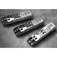
TXRX SMF LC 1.25GBD 2X5 EXT TEMP
Manufacturer
Avago Technologies US Inc.
Datasheet
1.HFCT-5911ATLZ.pdf
(16 pages)
Specifications of HFCT-5911ATLZ
Data Rate
1.25Gbps
Wavelength
1310nm
Applications
Ethernet
Voltage - Supply
3.1 V ~ 3.5 V
Connector Type
LC Duplex
Mounting Type
Through Hole
Supply Voltage
3.3V
Leaded Process Compatible
Yes
Lead Free Status / RoHS Status
Lead free / RoHS Compliant


Figure 7. Recommended Board Layout Hole Pattern
Electrical and Mechanical Interface Recommended Circuit
Figure 6 shows the recommended interface for deploying
the Avago Technologies transceivers in a +3.3 V system.
Data Line Interconnections
Avago Technologies’ HFCT-5911ATLZ fiber-optic trans-
ceivers are designed to couple to +3.3 V PECL signals. The
transmitter driver circuit regulates the output optical power.
The regulated light output will maintain a constant output
optical power provided the data pattern is balanced in duty
cycle. If the data duty cycle has long, continuous state times
(low or high data duty cycle), then the output optical power
will gradually change its average output optical power level
to its preset value.
The HFCT-5911ATLZ has a transmit disable function which is
a single-ended +3.3 V TTL input which is dc-coupled to Pin 8.
The receiver section is internally ac-coupled between the
preamplifier and the post-amplifier stages. The Data and
Data-bar outputs of the post-amplifier are internally biased
and ac-coupled to their respective output pins (Pins , 5).
8
NOTES:
1. THIS FIGURE DESCRIBES THE RECOMMENDED CIRCUIT BOARD LAYOUT FOR THE SFF TRANS-
2. THE HATCHED AREAS ARE KEEP-OUT AREAS RESERVED FOR HOUSING STANDOFFS. NO
3. 2 x 5 TRANSCEIVER MODULE REQUIRES 16 PCB HOLES (10 I/O PINS, 2 SOLDER POSTS AND
. THE MOUNTING STUDS SHOULD BE SOLDERED TO CHASSIS GROUND FOR MECHANICAL IN-
5. HOLES FOR HOUSING LEADS MUST BE TIED TO SIGNAL GROUND.
DIMENSIONS IN MILLIMETERS (INCHES)
(0.525)
(0.299)
13.34
7.59
CEIVER.
METAL TRACES OR GROUND CONNECTION IN KEEP-OUT AREAS.
PACKAGE GROUNDING TABS). PACKAGE GROUNDING TABS SHOULD BE CONNECTED TO SIG-
NAL GROUND.
TEGRITY AND TO ENSURE FOOTPRINT COMPATIBILITY WITH OTHER SFF TRANSCEIVERS.
2 x Ø 2.29 MAX.
(0.118)
3
(0.09)
2 x Ø 1.4 ±0.1
(0.055 ±0.004)
(0.236)
(0.118)
6
3
(0.28)
7.11
(0.18)
4.57
(0.700)
(0.055 ±0.004)
2 x Ø 1.4 ±0.1
17.8
4 x 1.78
(0.07)
(0.121)
3.08
(0.079)
(0.14)
3.56
2
10.16
(0.4)
(0.378)
Power Supply Filtering and Ground Planes
It is important to exercise care in circuit board layout to
achieve optimum performance from these transceivers.
Figure 6 shows the power supply circuit which complies
with the Small Form Factor Multisource Agreement. It is
further recommended that a continuous ground plane
be provided in the circuit board directly under the
transceiver to provide a low inductance ground for sig-
nal return current. This recommendation is in keeping
with good high frequency board layout practices.
Signal Detect is a single-ended, +3.3 V TTL compatible out-
put signal that is dc-coupled to Pin 3 of the module. Signal
Detect should not be ac-coupled externally to the follow-on
circuits because of its infrequent state changes.
Caution should be taken to account for the proper intercon-
nection between the supporting Physical Layer integrated
circuits and these transceivers. Figure 6 illustrates a recom-
mended interface circuit for interconnecting to a +3.3 V dc
PECL fiber-optic transceiver.
9.59
10 x Ø 0.81 ±0.1
(0.032 ±0.004)
2 x Ø 2.29
(0.09)
(0.055 ±0.004)
4 x Ø 1.4 ±0.1
(0.079)
2
Related parts for HFCT-5911ATLZ
Image
Part Number
Description
Manufacturer
Datasheet
Request
R

Part Number:
Description:
Fiber Optics, Transceiver Module
Manufacturer:
Avago Technologies US Inc.

Part Number:
Description:
Fiber Optic Transmitters, Receivers, Transceivers SFP OC12 IR Standard Delatch
Manufacturer:
Avago Technologies US Inc.

Part Number:
Description:
Manufacturer:
Avago Technologies
Datasheet:

Part Number:
Description:
155 Mb/s Single Mode Laser Transceiver For Atm, Sonet OC-3/SDH STM-1 (L1.1)
Manufacturer:
Agilent Technologies, Inc.
Datasheet:
Part Number:
Description:
Fiber Optics, Evaluation Kit
Manufacturer:
Avago Technologies US Inc.
Datasheet:
Part Number:
Description:
Fiber Optics, Evaluation Kit
Manufacturer:
Avago Technologies US Inc.
Datasheet:
Part Number:
Description:
Fiber Optics, Evaluation Kit
Manufacturer:
Avago Technologies US Inc.
Datasheet:

Part Number:
Description:
Agilent HFCT-5215B/D 155 Mb/s Single Mode Laser Transceiver
Manufacturer:
Hewlett-Packard
Datasheet:

Part Number:
Description:
Agilent HFCT-5905E MT-RJ Duplex Single Mode Transceiver
Manufacturer:
HP [Agilent(Hewlett-Packard)]
Datasheet:
Part Number:
Description:
LC TRANSCEIVER PORT PLUG
Manufacturer:
Avago Technologies US Inc.

Part Number:
Description:
OPTOCOUPLER GATE DRV 2A 16-SOIC
Manufacturer:
Avago Technologies US Inc.
Datasheet:
Part Number:
Description:
OPTOCOUPLER 2CH 2.5A 16-SOIC
Manufacturer:
Avago Technologies US Inc.
Datasheet:

Part Number:
Description:
OPTOCOUPLER GATE DRV 0.4A 16SOIC
Manufacturer:
Avago Technologies US Inc.
Datasheet:

Part Number:
Description:
OPTOCOUPLER 2.0A 250KHZ 8-DIP
Manufacturer:
Avago Technologies US Inc.
Datasheet:

Part Number:
Description:
OPTOCOUPLER 2.0A 250KHZ GW 8-SMD
Manufacturer:
Avago Technologies US Inc.
Datasheet: