HFCT-5911ATLZ Avago Technologies US Inc., HFCT-5911ATLZ Datasheet - Page 14
HFCT-5911ATLZ
Manufacturer Part Number
HFCT-5911ATLZ
Description
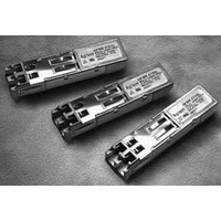
TXRX SMF LC 1.25GBD 2X5 EXT TEMP
Manufacturer
Avago Technologies US Inc.
Datasheet
1.HFCT-5911ATLZ.pdf
(16 pages)
Specifications of HFCT-5911ATLZ
Data Rate
1.25Gbps
Wavelength
1310nm
Applications
Ethernet
Voltage - Supply
3.1 V ~ 3.5 V
Connector Type
LC Duplex
Mounting Type
Through Hole
Supply Voltage
3.3V
Leaded Process Compatible
Yes
Lead Free Status / RoHS Status
Lead free / RoHS Compliant


Transmitter Optical Characteristics
T
Receiver Optical Characteristics
T
Notes:
1.
2.
3.
.
5.
6.
.
8.
1
Parameter
Receiver Overload
Receiver Sensitivity
Stressed Receiver Sensitivity
Stressed Receiver Eye Opening at TP
Receiver Electrical 3 dB Upper Cutoff Frequency
Operating Center Wavelength
Return Loss
Signal Detect - Asserted
Signal Detect - Deasserted
Signal Detect - Hysteresis
Parameter
Output Optical Power 9 µm SMF
Optical Extinction Ratio
Center Wavelength
Spectral Width - RMS
Optical Rise/Fall Time
Random Intensity Noise
Contributed Total Jitter added at TP2
Coupled Power Ratio 62.5 µm MMF
Coupled Power Ratio 50 µm MMF
C
C
= -10°C to +85°C, V
= -10°C to +85°C, V
The maximum Optical Output Power complies with IEEE 802.3 specification, and is class 1 laser eye safe.
These are unfiltered 20-80% values.
An eye diagram (Figure 9) specifies laser transmitter pulse response characteristics. The characteristics include rise time, fall time, pulse
undershoot, and ringing, all of which are controlled to prevent excessive degradation of the receiver sensitivity. The referenced Gigabit Eth-
ernet eye diagram using the required filter specifies these parameters. The output optical waveform complies with the requirements of the
eye mask discussed in section 38.6.5 and Fig. 38-2 of IEEE 802.3.
TP refers to the compliance point specified in 802.3, section 38.2.1.
The receiver sensitivity is measured using a worst case extinction ratio penalty while sampling at the center of the eye.
For a 2
The stressed receiver sensitivity is measured using the conformance test signal defined in 802.3, section 38.6.11. The conformance test signal
is conditioned by applying deterministic jitter and intersymbol interference.
The stressed receiver jitter is measured using the conformance test signal defined in 802.3, section 38.6.11 and set to an average optical
power 0.5 dB greater than the specified stressed receiver sensitivity.
In order to meet the 10 km link power budget the transmitter can trade off spectral width and center wavelength as shown in Figure 10.
-1 PRBS the receiver will provide output data with better than or equal to 1E-12 BER.
62.5 µm MMF
50 µm MMF
CC
CC
= 3.1 V to 3.5 V
= 3.1 V to 3.5 V
Symbol
P
ER
Cl
T
RIN
TJ
CPR
CPR
OUT
RISE/FALL
12
Symbol
P
P
l
P
P
P
A
A
IN
IN
D
C
- P
MIN
MAX
D
Min
-9.5
-11.5
-11.5
9
128
Min
-3
201
120
12
-30
1.5
Typ
1.
Typ
Max
-3
-3
-3
133
2.8
0.26
-120
22
28<CPR<0
12<CPR<20
Max
-20
-1.
1500
150
-20
Unit
dBm
dB
nm
nm
ns
dB/Hz
ps
Unit
dBm avg
dBm avg
dBm avg
ps
MHz
nm
dB
dBm avg
dBm avg
dB
Notes
1
8, Fig 10
8, Fig 10
2, 3, Fig 9
Reference
5
6,
,
Related parts for HFCT-5911ATLZ
Image
Part Number
Description
Manufacturer
Datasheet
Request
R

Part Number:
Description:
Fiber Optics, Transceiver Module
Manufacturer:
Avago Technologies US Inc.

Part Number:
Description:
Fiber Optic Transmitters, Receivers, Transceivers SFP OC12 IR Standard Delatch
Manufacturer:
Avago Technologies US Inc.

Part Number:
Description:
Manufacturer:
Avago Technologies
Datasheet:

Part Number:
Description:
155 Mb/s Single Mode Laser Transceiver For Atm, Sonet OC-3/SDH STM-1 (L1.1)
Manufacturer:
Agilent Technologies, Inc.
Datasheet:
Part Number:
Description:
Fiber Optics, Evaluation Kit
Manufacturer:
Avago Technologies US Inc.
Datasheet:
Part Number:
Description:
Fiber Optics, Evaluation Kit
Manufacturer:
Avago Technologies US Inc.
Datasheet:
Part Number:
Description:
Fiber Optics, Evaluation Kit
Manufacturer:
Avago Technologies US Inc.
Datasheet:

Part Number:
Description:
Agilent HFCT-5215B/D 155 Mb/s Single Mode Laser Transceiver
Manufacturer:
Hewlett-Packard
Datasheet:

Part Number:
Description:
Agilent HFCT-5905E MT-RJ Duplex Single Mode Transceiver
Manufacturer:
HP [Agilent(Hewlett-Packard)]
Datasheet:
Part Number:
Description:
LC TRANSCEIVER PORT PLUG
Manufacturer:
Avago Technologies US Inc.

Part Number:
Description:
OPTOCOUPLER GATE DRV 2A 16-SOIC
Manufacturer:
Avago Technologies US Inc.
Datasheet:
Part Number:
Description:
OPTOCOUPLER 2CH 2.5A 16-SOIC
Manufacturer:
Avago Technologies US Inc.
Datasheet:

Part Number:
Description:
OPTOCOUPLER GATE DRV 0.4A 16SOIC
Manufacturer:
Avago Technologies US Inc.
Datasheet:

Part Number:
Description:
OPTOCOUPLER 2.0A 250KHZ 8-DIP
Manufacturer:
Avago Technologies US Inc.
Datasheet:

Part Number:
Description:
OPTOCOUPLER 2.0A 250KHZ GW 8-SMD
Manufacturer:
Avago Technologies US Inc.
Datasheet: