NHD-10032AZ-FSY-GBW Newhaven Display, NHD-10032AZ-FSY-GBW Datasheet
NHD-10032AZ-FSY-GBW
Specifications of NHD-10032AZ-FSY-GBW


Related parts for NHD-10032AZ-FSY-GBW


NHD-10032AZ-FSY-GBW Summary of contents
Page 1
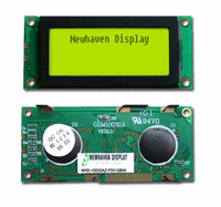
... User’s Guide NHD-10032AZ-FSY-GBW LCM (Liquid Crystal Display Graphic Module) RoHS Compliant Newhaven Display NHD- 100 x 32 pixels 10032- Version Line AZ- Transflective F- Side Yellow/Green LED B/L SY- STN- Gray G- 6:00 View B- Wide Temperature (-20 ~ +70c) W- For product support, contact Newhaven Display International, LLC ...
Page 2
... Mechanical diagram 1 Block diagram 2 Features 3 Mechanical specifications 4 Absolute maximum ratings 5 Description Of Terminals 6 DC Electrical Characteristics 7 Optical Characteristics 8 Timing Characteristics 9 Display command 10 Newhaven Display International, LLC CONTENTS Page ...
Page 3
... NHD-10032AZ-FSY-GBW 1 Mechanical diagram Newhaven Display International, LLC Page ...
Page 4
... NHD-10032AZ 3 Block diagram DB0~DB7 E1 R VDD VSS E2 VDD-Vo:LCD DRIVING VOLTAGE VR:10K~20K 4 Features Full dot-matrix structure with 100dots x 32 dots 1/32 duty ,1/5 bias STN LCD, positive Reflective LCD, yellow green 6 o’clock viewing angle 8 bits parallel data input 5 Mechanical specifications Outline dimension : 65.0mm(L) x 28.4mm (W) Viewing area : 46 ...
Page 5
... NHD-10032AZ 7 Description Of Terminals Pin Input/ Pin Name No. Output 1 VSS 2 VDD Input 5 R/W Input 6 E1 Input 7 E2 Input DB0-DB3 Input/output / DB4-DB7 Input/output Electrical Characteristics Parameter Supply voltage for LCD Input voltage Supply current Input leakage current “H” l evel input voltage “L” level input voltage “ ...
Page 6
... NHD-10032AZ 9 Optical Characteristics For TN Type Display Module (T Item Viewing angle Contrast ratio Response time(rise) Response time(fall) For STN Type Display Module (T Item Viewing angle Contrast ratio Response time(rise) Response time(fall) 10 Timing Characteristics MPU bus read/write 1(80-family MPU) A0. /CS t R/W DB0~DB7 WRITE ...
Page 7
... NHD-10032AZ Item System cycle time Address setup time Address hold time Data setup time Data hold time Control pulse width RD access time Output disable time MPU bus read/write 2(68-family MPU) E R/W A0. /CS DB0~DB7 WRITE DB0~DB7 READ Item System cycle time Address setup time ...
Page 8
... NHD-10032AZ 11 Display command Parameter A0 E R/W Display /OFF Display start line Set page address Set column (segment) address Read status Write 1 1 display 0 data Read display data Select ADC Static driver ON/OFF Select duty Read-modify write End Reset Table 3 is the command table. The SED1520 series identifies a data bus using a combination of A0 and R/W ( signals ...
Page 9
... NHD-10032AZ The command turns the display on and off D=1: display ON D=0: display OFF Display start line (C0H~DFH) This command specifies the line address shown if Figure 3 and indicates the display line that corresponds to COM0. the display area begins at the specified line address and continues the line address increment direction ...
Page 10
... NHD-10032AZ Set column address (00H~4FH) This command specifies a column address of the display data RAM. When the display data RAM is accessed by the MPU continuously, the column address is incremented by 1 each time it is accessed from the set address. Therefore, the MPU can access to data continuously. The column address stops to be incremented at address 80, and the page address is not changed continuously ...
Page 11
... NHD-10032AZ Write display data A0 E (RD) R/W (/WR Writes 8-bit of data into the display data RAM location specified by the contents of the column address and page address registers and then increments the column address register by one. Read display data A0 E (RD) R/W (/WR Reads 8-bit of data from the data I/O latch, updates the contents of the I/O latch with display data from the display data RAM location specified by the contents of the column address and page address registers and then increments the column address register ...
Page 12
... NHD-10032AZ Select duty (A8H; A9H (RD) R/W (/WR This command sets the duty cycle of the LCD drive and is only valid for the SED1520F and SED1522F.it is invalid for the SED1521F, which performs passive operation. The duty cycle of the SED1521F is determined by the externally generated FR signal. ...
Page 13
... NHD-10032AZ END (EEH (RD) R/W (/WR This command cancels read-modify-write mode and restores the contents of the column address register to their value prior to the receipt of the read-modify-write command. column address read-modify-write mode is selected Newhaven Display International, LLC set page address set column address read-modify-write ...
Page 14
... NHD-10032AZ RESET (E2H (RD) R/W (/WR This command clears The display start line register. And set page address register to 3 page. It does not affect the contents of the display data RAM. When the power supply is turned on, a Reset signal is entered in the RES pin. The Reset command cannot be used instead of this Reset signal ...