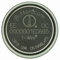
DS1996L-F5+ Maxim Integrated Products, DS1996L-F5+ Datasheet - Page 15

DS1996L-F5+
Manufacturer Part Number
DS1996L-F5+
Description
IBUTTON MEMORY 64KBit F5
Manufacturer
Maxim Integrated Products
Series
iButton®r
Datasheet
1.DS1996L-F5.pdf
(19 pages)
Specifications of DS1996L-F5+
Rohs Information
IButton RoHS Compliance Plan
Memory Size
8KB
Memory Type
NVRAM
Data Bus Width
64 bit
Interface Type
1-Wire
Maximum Operating Temperature
+ 70 C
Minimum Operating Temperature
- 40 C
Mounting Style
SMD/SMT
Package / Case
F5
Lead Free Status / RoHS Status
Lead free / RoHS Compliant
INITIALIZATION PROCEDURE “RESET AND PRESENCE PULSES” Figure 10
* In order not to mask interrupt signaling by other devices on the 1-Wire bus, t
less than 960 µs.
READ/WRITE TIME SLOTS
The definitions of write and read time slots are illustrated in Figure 11. All time slots are initiated by the
master driving the data line low. The falling edge of the data line synchronizes the DS1996 to the master
by triggering a delay circuit in the DS1996. During write time slots, the delay circuit determines when the
DS1996 will sample the data line. For a read data time slot, if a ”0” is to be transmitted, the delay circuit
determines how long the DS1996 will hold the data line low overriding the 1 generated by the master. If
the data bit is a ”1”, the iButton will leave the read data time slot unchanged.
READ/WRITE TIMING DIAGRAM Figure 11
Write-One Time Slot
RESISTOR
MASTER
DS1996
RESISTOR
MASTER
Regular Speed
480 µs ≤ t
480 µs ≤ t
15 µs ≤
60 µs ≤ t
Regular Speed
60 µs ≤ t
1 µs ≤ t
1 µs ≤ t
LOW1
REC
PDH
PDL
SLOT
RSTL
RSTH
< ∞
< 60 µs
< 240 µs
< 15 µs
< 120 µs
< ∞ *
< ∞ (includes recovery time)
15 of 19
Overdrive Speed
6 µs ≤ t
1 µs ≤ t
1 µs ≤ t
SLOT
LOW1
REC
< ∞
< 16 µs
< 2 µs
RSTL
Overdrive Speed
48 µs ≤ t
48 µs ≤ t
2 µs ≤ t
7 µs ≤ t
+ t
R
should always be
PDH
PDL
RSTL
RSTH
< 24 µs
< 6 µs
< 80 µs
< ∞
DS1996


