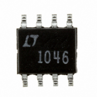
LTC1046CS8 Linear Technology, LTC1046CS8 Datasheet - Page 3

LTC1046CS8
Manufacturer Part Number
LTC1046CS8
Description
IC CMOS VOLT CONV SW-CAP 8-SOIC
Manufacturer
Linear Technology
Type
Switched Capacitor (Charge Pump), Divider, Invertingr
Datasheet
1.LTC1046CN8PBF.pdf
(12 pages)
Specifications of LTC1046CS8
Internal Switch(s)
Yes
Synchronous Rectifier
No
Number Of Outputs
1
Current - Output
50mA
Frequency - Switching
5.5kHz ~ 30kHz
Voltage - Input
1.5 ~ 6 V
Operating Temperature
0°C ~ 70°C
Mounting Type
Surface Mount
Package / Case
8-SOIC (3.9mm Width)
Output Voltage
-1.5 to -6/0.75 to 3V
Output Current
50mA
Operating Supply Voltage (min)
1.5V
Operating Supply Voltage (max)
6V
Operating Temp Range
0C to 70C
Operating Temperature Classification
Commercial
Package Type
SOIC N
Pin Count
8
Mounting
Surface Mount
Lead Free Status / RoHS Status
Contains lead / RoHS non-compliant
Voltage - Output
-
Power - Output
-
Lead Free Status / Rohs Status
Not Compliant
Available stocks
Company
Part Number
Manufacturer
Quantity
Price
Company:
Part Number:
LTC1046CS8
Manufacturer:
LINEAR
Quantity:
16 000
Part Number:
LTC1046CS8
Manufacturer:
LINEAR/凌特
Quantity:
20 000
Company:
Part Number:
LTC1046CS8#PBF
Manufacturer:
LTC
Quantity:
810
Part Number:
LTC1046CS8#PBF
Manufacturer:
LINEAR/凌特
Quantity:
20 000
Company:
Part Number:
LTC1046CS8#TR
Manufacturer:
LT
Quantity:
623
Part Number:
LTC1046CS8#TRPBF
Manufacturer:
LT/凌特
Quantity:
20 000
TYPICAL PERFOR
ELECTRICAL C
Note 1: Absolute Maximum Ratings are those values beyond which
the life of the device may be impaired.
Note 2: Connecting any input terminal to voltages greater than V
less than ground may cause destructive latch-up. It is recommended
that no inputs from sources operating from external supplies be
applied prior to power-up of the LTC1046.
500
400
300
200
100
100
90
80
70
60
50
40
30
20
10
0
0
100
Output Resistance vs
Oscillator Frequency
Power Conversion Efficiency vs
Load Current for V
0
1
C1 = C2
= 100 F
OSCILLATOR FREQUENCY, f
2
LOAD CURRENT, I
3
1k
4
C1 = C2
= 10 F
5
+
I
P
S
HARA TERISTICS
= 2V
EFF
6
L
10k
T
V
C1 = C2 = 10 F
f
OSC
(mA)
A
+
7
C1 = C2
= 1 F
OSC
= 25 C
= 2V
W
T
V
I
= 8kHz
L
A
+
8
(Hz)
= 10mA
= 25 C
= 5V
A
1046 G01
1046 G04
C
9
U
100k
10
CE
10
9
8
7
6
5
4
3
2
1
0
C
1000
100
HARA TERISTICS
100
90
80
70
60
50
40
30
20
10
10
0
0
Power Conversion Efficiency vs
Load Current for V
0
Output Resistance vs
Supply Voltage
T
I
L
A
= 3mA
= 25 C
+
10
1
C
or
OSC
C
LOAD CURRENT, I
SUPPLY VOLTAGE, V
20
= 0pF
2
C
OSC
30
3
= 100pF
P
EFF
Note 3: R
Note 4: f
fixture capacitance loading. The 0pF frequency is correlated to this 100pF
test point, and is intended to simulate the capacitance at pin 7 when the
device is plugged into a test socket and no external capacitor is used.
I
+
S
40
4
= 5V
L
T
V
C1 = C2 = 10 F
f
OSC
A
(mA)
+
+
50
= 25 C
= 5V
5
(V)
= 30kHz
OSC
OUT
60
is tested with C
6
(Using Test Circuit in Figure 1)
1046 G05
is measured at T
1046 G02
70
7
100
90
80
70
60
50
40
30
20
10
0
OSC
100
80
70
60
50
40
30
20
10
98
96
94
92
90
88
86
84
82
80
J
= 25 C immediately after power-on.
–55
100
= 100pF to minimize the effects of test
Output Resistance vs
Temperature
Power Conversion Efficiency vs
Oscillator Frequency
C1 = C2 = 10 F
V
–25
A
OSCILLATOR FREQUENCY, f
+
= 2V, C
C
AMBIENT TEMPERATURE ( C)
1k
0
B
OSC
V
+
25
E
= 0pF
= 5V, C
D
10k
50
LTC1046
OSC
A = 100 F, 1mA
B = 100 F, 15mA
C = 10 F, 1mA
D = 10 F, 15mA
E = 1 F, 1mA
F = 1 F, 15mA
= 0pF
75
100k
OSC
F
V
T
C1 = C2
A
(Hz)
+
100
= 25 C
= 5V
1046 G03
1046 G06
1046fb
3
125
1M


