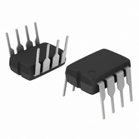
LM2574N-3.3G ON Semiconductor, LM2574N-3.3G Datasheet - Page 2

LM2574N-3.3G
Manufacturer Part Number
LM2574N-3.3G
Description
IC REG SW 0.5A 3.3V OUTPUT 8-DIP
Manufacturer
ON Semiconductor
Type
Step-Down (Buck)r
Specifications of LM2574N-3.3G
Internal Switch(s)
Yes
Synchronous Rectifier
No
Number Of Outputs
1
Voltage - Output
3.3V
Current - Output
500mA
Frequency - Switching
52kHz
Voltage - Input
4.75 ~ 40 V
Operating Temperature
-40°C ~ 125°C
Mounting Type
Through Hole
Package / Case
8-DIP (0.300", 7.62mm)
Output Voltage
3.3 V
Output Current
0.5 A
Input Voltage
4.75 V to 40 V
Switching Frequency
52 KHz
Operating Temperature Range
- 40 C to + 125 C
Mounting Style
Through Hole
Duty Cycle (max)
98 %
Current, Input Bias
25 nA
Current, Output
0.5 A
Current, Supply
5 mA
Frequency, Oscillator
52 kHz
Package Type
PDIP-8
Regulator Type
Switching
Resistance, Thermal, Junction To Case
5 °C/W
Temperature, Operating, Range
-40 to +125 °C
Voltage, Output
3.3 V
Voltage, Supply
40 V
Lead Free Status / RoHS Status
Lead free / RoHS Compliant
Power - Output
-
Lead Free Status / Rohs Status
Lead free / RoHS Compliant
Other names
LM2574N-3.3G
LM2574N-3.3GOS
LM2574N-3.3GOS
Unregulated
Maximum ratings are those values beyond which device damage can occur. Maximum ratings applied to the device are individual stress limit
values (not normal operating conditions) and are not valid simultaneously. If these limits are exceeded, device functional operation is not implied,
damage may occur and reliability may be affected.
NOTE: ESD data available upon request.
ABSOLUTE MAXIMUM RATINGS
DC Input
Maximum Supply Voltage
ON/OFF Pin Input Voltage
Output Voltage to Ground (Steady State)
DW Suffix, Plastic Package Case 751G
Max Power Dissipation
N Suffix, Plastic Package Case 626
Max Power Dissipation
Storage Temperature Range
Minimum ESD Rating
Lead Temperature (Soldering, 10 seconds)
Maximum Junction Temperature
Thermal Resistance, Junction−to−Air
Thermal Resistance, Junction−to−Ambient
Thermal Resistance, Junction−to−Case
(Human Body Model: C = 100 pF, R = 1.5 kW)
C
in
Feedback
Unregulated
Sig Gnd
7.0 − 40 V
DC Input
+V
(4)
5
1
2
in
(12)
(3)
22 mF
Rating
R2
R1
1.0 k
C
Band−Gap
Reference
Representative Block Diagram and Typical Application
in
1.235 V
Typical Application (Fixed Output Voltage Versions)
NOTE: Pin numbers in ( ) are for the SO−16W package.
Figure 1. Block Diagram and Typical Application
Fixed Gain
Error Amplifier
(Absolute Maximum Ratings indicate limits beyond which damage to the device may occur).
18 kHz
(12)
+V
Freq
Shift
in
5
2
(4)
Oscillator
52 kHz
Sig
Gnd
Comparator
3.1 V Internal
LM2574, NCV2574
Regulator
LM2574
4
http://onsemi.com
(6)
Pwr
Gnd
3
(5)
2
Reset
Latch
(14)
ON/OFF
(3)
Current
Limit
ON/OFF
Output
Feedback
1
7
Symbol
Shutdown
Thermal
Driver
R
R
R
T
V
P
P
T
qJA
qJA
qJC
stg
−
−
−
−
D1
1N5819
in
D
D
J
330 mH
L1
1.0 Amp
Switch
C
220 mF
out
−0.3 V ≤ V ≤ +V
Internally Limited
Internally Limited
−65°C to +150°C
(5)
(6)
ON/OFF
3
Output
7
Pwr Gnd
4
5.0 V Regulated
Output 0.5 A Load
(14)
Value
−1.0
145
100
260
150
5.0
2.0
45
Voltage Versions
For adjustable version
R1 = open, R2 = 0 W
in
D1
Output
3.3 V
5.0 V
12 V
15 V
L1
C
out
°C/W
°C/W
°C/W
Unit
°C
kV
°C
°C
W
W
V
V
V
8.84 k
11.3 k
1.7 k
3.1 k
(W)
R2
Load
V
out


