AD652AQ Analog Devices Inc, AD652AQ Datasheet - Page 8
AD652AQ
Manufacturer Part Number
AD652AQ
Description
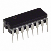
IV V-F CONVERTER SYNC 16-CDIP
Manufacturer
Analog Devices Inc
Type
Voltage to Frequencyr
Specifications of AD652AQ
Rohs Status
RoHS non-compliant
Frequency - Max
2MHz
Full Scale
±50ppm/°C
Linearity
±0.02%
Mounting Type
Through Hole
Package / Case
16-CDIP (0.300", 7.62mm)
Full Scale Range
1MHz To 2MHz
Linearity %
0.02%
Supply Voltage Range
± 6V To ± 18V
Digital Ic Case Style
DIP
No. Of Pins
16
Frequency Max
2MHz
Termination Type
Through Hole
Converter Function
VFC
Full Scale Frequency
2000
Power Supply Requirement
Single/Dual
Single Supply Voltage (max)
36V
Single Supply Voltage (min)
12V
Dual Supply Voltage (typ)
±15V
Dual Supply Voltage (min)
±6V
Dual Supply Voltage (max)
±18V
Operating Temperature (min)
-40C
Operating Temperature (max)
85C
Operating Temperature Classification
Industrial
Package Type
CDIP
Converter Type
Voltage to Frequency
Current, Quiescent Supply
±11 mA (Typ.)
Frequency Range
5 MHz (Typ.)
Input Impedance
20 Kiloohms
Number Of Pins
20
Temperature, Operating, Maximum
85 °C
Temperature, Operating, Minimum
-40 °C
Voltage, Range
±6 to ±18 V
Voltage, Supply
36 V
Filter Terminals
Through Hole
Rohs Compliant
No
Calibration Error Fs Typ
5%
Lead Free Status / Rohs Status
Not Compliant
Available stocks
Company
Part Number
Manufacturer
Quantity
Price
Company:

Part Number:
AD652AQ
Manufacturer:
TOSHIBA
Quantity:
670


AD652
Another way to view this is that the output is a frequency of
approximately one-quarter of the clock that has been phase
modulated. A constant frequency can be thought of as
accumulating phase linearly with time at a rate equal to 2πf
radians per second. Therefore, the average output frequency,
which is slightly in excess of a quarter of the clock, requires
phase accumulation at a certain rate. However, since the SVFC
is running at exactly one-quarter of the clock, it does not
accumulate enough phase (see Figure 7). When the difference
between the required phase (average frequency) and the actual
phase equals 2π, a step-in phase is taken where the deficit is
made up instantaneously. The output frequency is then a steady
carrier that has been phase modulated by a sawtooth signal (see
Figure 7). The period of the sawtooth phase modulation is the
time required to accumulate a 2π difference in phase between
the required average frequency and one quarter of the clock
frequency. The sawtooth phase modulation amplitude is 2π.
2
2
2
π
π
π
PHASE
φ
MOD (t)
V
OUT
CARRIER FREQUENCY
EXPECTED
(t) = COS (2
Figure 7. Phase Modulation
PHASE
AVERAGE
π × f
ACTUAL PHASE
AVE
×
t +
φ
PHASE
MODULATION
MOD (t))
TIME
TIME
Rev. C | Page 8 of 28
The result of this synchronism is that the rate at which data may
be extracted from the series bit stream produced by the SVFC is
limited. The output pulses are typically counted during a fixed
gate interval and the result is interpreted as an average
frequency. The resolution of such a measurement is determined
by the clock frequency and the gate time. For example, if the
clock frequency is 4 MHz and the gate time is 4.096 ms, a
maximum count of 8,192 is produced by a full-scale frequency
of 2 MHz. Thus, the resolution is 13 bits.
OVERRANGE
Since each reset pulse is only one clock period in length, the
full-scale output frequency is equal to one-half the clock
frequency. At full scale, the current steering switch spends half
of the time on the summing junction; thus, an input current of
0.5 mA can be balanced. In the case of an overrange, the output
of the integrator op amp drifts in the negative direction and the
output of the comparator remains high. The logic circuits
simply settle into a divide-by-two of the clock state.
Related parts for AD652AQ
Image
Part Number
Description
Manufacturer
Datasheet
Request
R

Part Number:
Description:
±1.7g Dual-Axis IMEMS Accelerometer Evaluation Board
Manufacturer:
Analog Devices Inc
Datasheet:

Part Number:
Description:
Inertial Sensor Evaluation System
Manufacturer:
Analog Devices Inc
Datasheet:
Part Number:
Description:
Manufacturer:
Analog Devices Inc
Datasheet:
Part Number:
Description:
Manufacturer:
Analog Devices Inc
Datasheet:
Part Number:
Description:
Manufacturer:
Analog Devices Inc
Datasheet:
Part Number:
Description:
Manufacturer:
Analog Devices Inc
Datasheet:
Part Number:
Description:
Manufacturer:
Analog Devices Inc
Datasheet:
Part Number:
Description:
Manufacturer:
Analog Devices Inc
Datasheet:
Part Number:
Description:
Manufacturer:
Analog Devices Inc
Datasheet:
Part Number:
Description:
Manufacturer:
Analog Devices Inc
Datasheet:
Part Number:
Description:
Manufacturer:
Analog Devices Inc
Datasheet:
Part Number:
Description:
Manufacturer:
Analog Devices Inc
Datasheet:
Part Number:
Description:
Manufacturer:
Analog Devices Inc
Datasheet: