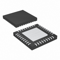
MAX1702BETX+ Maxim Integrated Products, MAX1702BETX+ Datasheet

MAX1702BETX+
Specifications of MAX1702BETX+
Related parts for MAX1702BETX+
MAX1702BETX+ Summary of contents
Page 1
... Intel is a registered trademark of Intel Corporation. XScale is a trademark of Intel Corporation. ARM and ARM Powered are registered trademarks of ARM Limited. ________________________________________________________________ Maxim Integrated Products For pricing, delivery, and ordering information, please contact Maxim/Dallas Direct! at 1-888-629-4642, or visit Maxim’s website at www.maxim-ic.com. Microprocessor-Based Systems ...
Page 2
Triple-Output Power-Management IC for Microprocessor-Based Systems ABSOLUTE MAXIMUM RATINGS IN, FB2, OUT3, COMP1, COMP2, COMP3, PGM3, ON2, LBO, OUTOK, RSO, MR, LBI, DBI, OUT1 to GND .......................................................-0.3V to +6V REF to GND ...................................................-0 INP1, INP2, INP3 to IN...........................................-0.3V ...
Page 3
Triple-Output Power-Management IC for ELECTRICAL CHARACTERISTICS (continued 3.6V, V INP1 INP2 INP3 IN +85°C unless otherwise noted. Typical values are at T PARAMETER OUT1 Discharge Resistance V OUT1 SYNCHRONOUS BUCK REGULATOR 2 ...
Page 4
Triple-Output Power-Management IC for Microprocessor-Based Systems ELECTRICAL CHARACTERISTICS (continued 3.6V, V INP1 INP2 INP3 IN LBI +85°C unless otherwise noted. Typical values are at T PARAMETER Current-Sense Transresistance P-Channel Current-Limit Threshold P-Channel ...
Page 5
Triple-Output Power-Management IC for ELECTRICAL CHARACTERISTICS (continued 3.6V, V INP1 INP2 INP3 IN +85°C unless otherwise noted. Typical values are at T PARAMETER 2.6V ≤ V RSO, LBO, OUTOK Output Low Level ...
Page 6
Triple-Output Power-Management IC for Microprocessor-Based Systems (Circuit of Figure +25°C, unless otherwise noted.) A REG1 EFFICIENCY vs. LOAD CURRENT 100 100 1000 LOAD CURRENT (mA) ...
Page 7
Triple-Output Power-Management IC for (Circuit of Figure +25°C, unless otherwise noted.) A REG3 OUTPUT VOLTAGE vs. LOAD CURRENT (V 2.515 2.510 T = +85°C A 2.505 2.500 2.495 2.490 T = -40°C 2.485 A 2.480 2.475 0 ...
Page 8
Triple-Output Power-Management IC for Microprocessor-Based Systems REG3 HEAVY-LOAD SWITCHING WAVEFORM LOAD = 700mA 400ns/div REG3 MEDIUM-LOAD SWITCHING WAVEFORM LOAD = 100mA 2µs/div REG2 LIGHT-LOAD SWITCHING WAVEFORM LOAD = 10mA ...
Page 9
Triple-Output Power-Management IC for (Circuit of Figure +25°C, unless otherwise noted.) A TURN-ON SEQUENCE FROM POWER APPLICATION I = 250mA 100mA, I LOAD1 LOAD2 20ms/div TURN-ON DELAY I = ...
Page 10
Triple-Output Power-Management IC for Microprocessor-Based Systems (Circuit of Figure +25°C, unless otherwise noted.) A REG2 LOAD TRANSIENT WAVEFORM LOAD = 20mA TO 200mA 40µs/div LINE TRANSIENT RESPONSE WAVEFORM 5V, ...
Page 11
Triple-Output Power-Management IC for PIN NAME 1, 9, 13, 18, 19, 26, 27, N.C. No Connection. These pins are not internally connected. 31, 35 Low-Battery Input. Connect a resistive voltage-divider from the battery voltage to LBI to set the low- ...
Page 12
Triple-Output Power-Management IC for Microprocessor-Based Systems PIN NAME REG1 Output-Voltage Sense Input. Bypass OUT1 to PG1 with a 10µF or greater low-ESR capacitor 20 OUT1 (see the Output Capacitor Selection section). REG2 Compensation Node. Connect a series resistor and capacitor ...
Page 13
Triple-Output Power-Management IC for Functional Diagram MAX1702B DEAD- DBI BATTERY DBO DETECTOR EN LBI LOW- REF BATTERY DETECTOR LBO POK ON/OFF OUTOK CONTROL EN LOGIC ON2 REF RSO EN RESET TIMER MR REF BANDGAP REFERENCE GND REF Detailed Description The ...
Page 14
Triple-Output Power-Management IC for Microprocessor-Based Systems high-side P-channel MOSFET turns on, and the con- troller enters a low-current consumption mode. The device remains in this mode until the MAX1702B is no longer in dropout. Synchronous Rectification An N-channel synchronous rectifier ...
Page 15
Triple-Output Power-Management IC for Compensation and Stability Compensate each regulator by placing a resistor and a capacitor in series, from COMP_ to GND and connect a 33pF capacitor from COMP_ to GND for improved noise immunity (Figure 1). The capacitor ...
Page 16
Triple-Output Power-Management IC for Microprocessor-Based Systems Table 1. Suggested Inductors MANUFACTURER PART NUMBER Coilcraft DO1606 Coilcraft LPT1606-472 Sumida CDRH4D28-4R7 Sumida CDRH5D18-4R1 Sumida CR43 The inductor current becomes discontinuous if I decreases to LIR/2 from the output current value used to ...
Page 17
Triple-Output Power-Management IC for INPUT 2.6V TO 5.5V OUT1 Figure 1. Typical Operating Circuit ______________________________________________________________________________________ Microprocessor-Based Systems 4.7µF IN INP1 INP2 R1 162kΩ DBI R2 53.6kΩ LBI R3 86.6kΩ MAX1702B LBO 100kΩ 100kΩ OUTOK ON2 OUT1 100kΩ RSO MR GND ...
Page 18
Triple-Output Power-Management IC for Microprocessor-Based Systems (The package drawing(s) in this data sheet may not reflect the most current specifications. For the latest package outline information www.maxim-ic.com/packages.) 18 ______________________________________________________________________________________ Package Information ...
Page 19
... Maxim cannot assume responsibility for use of any circuitry other than circuitry entirely embodied in a Maxim product. No circuit patent licenses are implied. Maxim reserves the right to change the circuitry and specifications without notice at any time. Maxim Integrated Products, 120 San Gabriel Drive, Sunnyvale, CA 94086 408-737-7600 ____________________ 19 © 2002 Maxim Integrated Products ...


