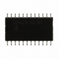
UDN2916LBTR-T Allegro Microsystems Inc, UDN2916LBTR-T Datasheet - Page 2

UDN2916LBTR-T
Manufacturer Part Number
UDN2916LBTR-T
Description
IC MOTOR DRIVER PWM DUAL 24SOIC
Manufacturer
Allegro Microsystems Inc
Datasheet
1.UDN2916LBTR-T.pdf
(10 pages)
Specifications of UDN2916LBTR-T
Applications
DC Motor Driver, Stepper Motor Driver
Number Of Outputs
2/1
Current - Output
±750mA
Voltage - Load
10 V ~ 45 V
Voltage - Supply
4.75 V ~ 5.25 V
Operating Temperature
-20°C ~ 85°C
Mounting Type
Surface Mount
Package / Case
24-SOIC (7.5mm Width)
Motor Type
Full Bridge
No. Of Outputs
2
Output Current
750mA
Output Voltage
45V
Supply Voltage Range
4.75V To 5.25V
Driver Case Style
SOIC
No. Of Pins
24
Lead Free Status / RoHS Status
Lead free / RoHS Compliant
Other names
620-1156-2
UDN2916LBTR-T
UDN2916LBTR-T
Available stocks
Company
Part Number
Manufacturer
Quantity
Price
Company:
Part Number:
UDN2916LBTR-T
Manufacturer:
MIT
Quantity:
6 223
Part Number:
UDN2916LBTR-T
Manufacturer:
ALLEGRO/雅丽高
Quantity:
20 000
Features and Benefits
▪ 750 mA continuous output current
▪ 45 V output sustaining voltage
▪ Internal clamp diodes
▪ Internal PWM current control
▪ Low output saturation voltage
▪ Internal thermal shutdown circuitry
▪ Similar to dual PBL3717 or UC3770
Packages
29319.20R
with internally-fused leads
Package EB 44-pin PLCC
Package B 24-pin
Package LB 24-pin
Batwing SOICW
Batwing DIP
I
I
'B' PACKAGE,
CHANNEL 1
PIN NUMBERS
SHOWN.
0
1
20
17
Not to scale
40 k
V
REF
15
20 k
PWM Current-Control Circuitry
10 k
Dual Full-Bridge PWM Motor Driver
10
OUT A
1
R
S
V
24
23
BB
E
OUT B
R C
Description
The UDx2916 motor drivers drive both windings of a bipolar
stepper motor or bidirectionally control two DC motors.
Both bridges are capable of sustaining 45 V and include
internal pulse-width modulation (PWM) control of the
output current to 750 mA. The outputs have been optimized
for a low output saturation voltage drop (less than 1.8 V
total source plus sink at 500 mA).
For PWM current control, the maximum output current is
determined by user selection of a reference voltage and sensing
resistor. Two logic-level inputs select output current limits of
0%, 33%, 67%, or 100% of the maximum level. A PHASE
input to each bridge determines load current direction.
The bridges include both ground-clamp and flyback diodes for
protection against inductive transients. Internally generated
delays prevent crossover currents when switching current
direction. Special power-up sequencing is not required. Thermal
protection circuitry disables the outputs if the chip temperature
exceeds safe operating limits.
The device is supplied in a 24-pin dual in-line plastic (DIP,
package B) with two pairs of batwing leads as heat-sinkable
tabs for enhanced power dissipation capabilities. The LB
package is a 24-lead surface-mount wide SOIC with two pairs
Continued on the next page…
21
SENSE
22
C
–
+
C
R
T
SHOT
ONE
14
RC
C
T
Dwg. EP-007B
SOURCE
DISABLE
2916


