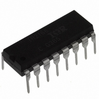
IR2166PBF International Rectifier, IR2166PBF Datasheet - Page 25

IR2166PBF
Manufacturer Part Number
IR2166PBF
Description
IC CONTROLLER PFC/BALLAST 16DIP
Manufacturer
International Rectifier
Type
PFC/Ballast Controllerr
Datasheet
1.IR2166STRPBF.pdf
(32 pages)
Specifications of IR2166PBF
Frequency
39 ~ 50 kHz
Current - Supply
10mA
Current - Output
400mA
Voltage - Supply
11.5 V ~ 15.6 V
Operating Temperature
-25°C ~ 125°C
Package / Case
16-DIP (0.300", 7.62mm)
Package
16-pin DIP
Circuit
Fluorescent Ballast IC
Offset Voltage (v)
600
Output Source Current Min (ma)
250
Output Sink Current Min (ma)
400
Vcc Range (v)
10-25V with UVLO
Output Voltage Min (v)
10
Output Voltage Max (v)
25
Pbf
PbF Option Available
Lead Free Status / RoHS Status
Lead free / RoHS Compliant
Other names
*IR2166PBF
Available stocks
Company
Part Number
Manufacturer
Quantity
Price
Part Number:
IR2166PBF
Manufacturer:
IR
Quantity:
20 000
On-time Modulation
A fixed on-time of MPFC over an entire cycle of
the line input voltage produces a peak inductor
current which naturally follows the sinusoidal
shape of the line input voltage. The smoothed
averaged line input current is in phase with the
line input voltage for high power factor but the
total harmonic distortion (THD), as well as the
individual higher harmonics, of the current can
still be too high. This is mostly due to cross-
over distortion of the line current near the zero-
crossings of the line input voltage. To achieve
low harmonics which are acceptable to
international standard organizations and general
market requirements, an additional on-time
www.irf.com
I
PFC
LPFC
pin
pin
ZX
Figure 10: LPFC current, PFC pin and ZX pin timing
0
0
0
diagram.
modulation circuit has been added to the PFC
control. This circuit dynamically increases the
on-time of MPFC as the line input voltage nears
the zero-crossings (Figure 11). This causes the
peak LPFC current, and therefore the smoothed
line input current, to increase slightly higher near
the zero-crossings of the line input voltage. This
reduces the amount of cross-over distortion in
the line input current which reduces the THD
and higher harmonics to low levels.
I
PFC
Over-voltage Protection (OVP)
Should over-voltage occur on the DC bus
causing the VBUS pin to exceed the internal 4.3V
threshold, the PFC output is disabled (set to a
logic 'low'). When the DC bus decreases again
causing the VBUS pin to decrease below the
internal 4V threshold, a watch-dog pulse is forced
on the PFC pin and normal PFC operation is
resumed.
Under-voltage Reset (UVR)
When the line input voltage is decreased,
interrupted or a brown-out condition occurs, the
PFC feedback loop causes the on-time of MPFC
LPFC
pin
Figure 11: On-time modulation near the zero-crossings.
0
0
near peak region of
rectified AC line
IR2166 & (PbF)
near zero-crossing region
of rectified AC line
25


