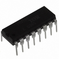
IR2166PBF International Rectifier, IR2166PBF Datasheet - Page 22

IR2166PBF
Manufacturer Part Number
IR2166PBF
Description
IC CONTROLLER PFC/BALLAST 16DIP
Manufacturer
International Rectifier
Type
PFC/Ballast Controllerr
Datasheet
1.IR2166STRPBF.pdf
(32 pages)
Specifications of IR2166PBF
Frequency
39 ~ 50 kHz
Current - Supply
10mA
Current - Output
400mA
Voltage - Supply
11.5 V ~ 15.6 V
Operating Temperature
-25°C ~ 125°C
Package / Case
16-DIP (0.300", 7.62mm)
Package
16-pin DIP
Circuit
Fluorescent Ballast IC
Offset Voltage (v)
600
Output Source Current Min (ma)
250
Output Sink Current Min (ma)
400
Vcc Range (v)
10-25V with UVLO
Output Voltage Min (v)
10
Output Voltage Max (v)
25
Pbf
PbF Option Available
Lead Free Status / RoHS Status
Lead free / RoHS Compliant
Other names
*IR2166PBF
Available stocks
Company
Part Number
Manufacturer
Quantity
Price
Part Number:
IR2166PBF
Manufacturer:
IR
Quantity:
20 000
lower than the minimum specified ballast input
voltage. This hysteresis will result in clean turn-
on and turnoff of the ballast.
CS and EOL Fault Mode (FAULT)
Should the voltage at the SD/EOL pin exceed 3V
or decrease below 1V during RUN mode, the IC
enters fault mode and all gate driver outputs, HO,
LO and PFC, are latched off in the 'low' state.
CPH is discharged to COM for resetting the
preheat time, and CT is discharged to COM for
disabling the oscillator. To exit fault mode, VCC
must be recycled back below the UVLO negative-
going turn-off threshold, or, the shutdown pin, SD,
must be pulled above 5.2 volts. Either of these
will force the IC to enter UVLO mode (see State
Diagram, page 7). Once VCC is above the turn-
on threshold and SD is below 5.0 volts, the IC
will begin oscillating again in the preheat mode.
The current sense function will force the IC to
enter FAULT mode only after the voltage at the
current sense pin has been pulsed about 25 times
with a voltage greater than 1.3 volts during preheat
and ignition modes only. These over-currents must
occur during the on-time of LO. During run mode,
a single pulse on the CS pin above 1.3V will force
the IC to enter FAULT mode.
IR2166 & (PbF)
22
CS
LO
2.0V
Figure 5: FAULT counter during preheat and ignition
Run Mode
25 Pulses
Fault Mode
II. PFC Section Functional Description
In most electronic ballasts it is necessary to
have the circuit act as a pure resistive load to
the AC input line voltage. The degree to which
the circuit matches a pure resistor is measured
by the phase shift between the input voltage
and input current and how well the shape of the
input current waveform matches the shape of
the sinusoidal input voltage. The cosine of the
phase angle between the input voltage and input
current is defined as the power factor (PF), and
how well the shape of the input current waveform
matches the shape of the input voltage is
determined by the total harmonic distortion
(THD). A power factor of 1.0 (maximum)
corresponds to zero phase shift and a THD of
0% represents a pure sinewave (no distortion).
For this reason it is desirable to have a high PF
and a low THD. To achieve this, the IR2166
includes an active power factor correction (PFC)
circuit which, for an AC line input voltage,
produces an AC line input current. The control
method implemented in the IR2166 is for a boost-
type converter (Figure 6) running in critical-
conduction mode (CCM). This means that during
each switching cycle of the PFC MOSFET, the
circuit waits until the inductor current discharges
to zero before turning the PFC MOSFET on again.
The PFC MOSFET is turned on and off at a
much higher frequency (>10KHz) than the line
input frequency (50 to 60Hz).
Figure 6: Boost-type PFC circuit
(+)
(-)
LPFC
MPFC
DPFC
+
CBUS
DC Bus
www.irf.com


