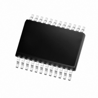
MCP3905A-I/SS Microchip Technology, MCP3905A-I/SS Datasheet - Page 16

MCP3905A-I/SS
Manufacturer Part Number
MCP3905A-I/SS
Description
IC POWER METERING-1 PHASE 24SSOP
Manufacturer
Microchip Technology
Specifications of MCP3905A-I/SS
Input Impedance
390 KOhm
Measurement Error
0.1%
Voltage - I/o High
2.4V
Voltage - I/o Low
0.85V
Current - Supply
2.7mA
Voltage - Supply
4.5 V ~ 5.5 V
Operating Temperature
-40°C ~ 85°C
Mounting Type
Surface Mount
Package / Case
24-SSOP (0.200", 5.30mm Width)
Meter Type
Single Phase
Brief Features
Active Real Power Pulse Output, Ultra Low Drift
Supply Voltage Range
4.5V To 5.5V
Operating Temperature Range
-40°C To +85°C
Digital Ic Case Style
SSOP
No. Of Pins
24
Svhc
No
Ic Function
Single Phase Energy Metering
Rohs Compliant
Yes
Lead Free Status / RoHS Status
Lead free / RoHS Compliant
For Use With
MCP3905RD-PM1 - REFERENCE DESIGN FOR MCP3905MCP3905EV - BOARD DEMO FOR MCP3905
Lead Free Status / Rohs Status
Lead free / RoHS Compliant
Available stocks
Company
Part Number
Manufacturer
Quantity
Price
Company:
Part Number:
MCP3905A-I/SS
Manufacturer:
MICROCHIP
Quantity:
12 000
Part Number:
MCP3905A-I/SS
Manufacturer:
MICROCHIP/微芯
Quantity:
20 000
MCP3905A/05L/06A
The
integration times and, thus, higher frequencies. The
output frequency value can be calculated with the
following equation:
EQUATION 4-2:
The constant HF
digital settings with the
The detailed timings of the output pulses are described
in the Timing Characteristics table (see Section 1.0
“Electrical Characteristics” and
TABLE 4-3:
TABLE 4-4:
DS22011A-page 16
Where:
F2
F2
0
0
0
0
1
1
1
1
0
0
0
0
1
1
1
1
V
V
G is the PGA gain on channel 0 (current channel)
HF
V
high-frequency
0
1
REF
HF
C
is the RMS differential voltage on channel 0
is the RMS differential voltage on channel 1
F1
F1
0
0
1
1
0
0
1
1
0
0
1
1
0
0
1
1
is the frequency constant selected
OUT
is the voltage reference
(
Hz
F0
F0
0
1
0
1
0
1
0
1
0
1
0
1
0
1
0
1
C
)
MCP3905L OUTPUT FREQUENCY SETTINGS
MCP3905A/06A OUTPUT FREQUENCY SETTINGS
depends on the F
=
2048XF
2048XF
8.06 V
--------------------------------------------------------------- -
HF
OUTPUT EQUATION
128XF
Table
64XF
32XF
16XF
64XF
32XF
16XF
64XF
32XF
16XF
64XF
32XF
16XF
output
8XF
HF
HF
OUT
×
C
C
C
C
C
C
C
C
C
C
C
C
C
C
C
4-4.
C
0
C
C
(
FREQUENCY
V
×
HF
REF
V
Figure
1
MCLK/2
MCLK/2
MCLK/2
MCLK/2
MCLK/2
MCLK/2
MCLK/2
MCLK/2
MCLK/2
MCLK/2
MCLK/2
MCLK/2
MCLK/2
MCLK/2
MCLK/2
MCLK/2
HF
HF
OUT
×
)
2
OUT0
G
C
C
×
(Hz)
(Hz)
1-1).
HF
has
15
15
15
16
16
16
16
15
15
15
14
14
14
14
and F
7
7
C
lower
OUT1
HF
3.58 MHz
HF
3.58 MHz
27968.75
27968.75
MCLK=
MCLK=
109.25
109.25
109.25
109.25
109.25
109.25
219.51
219.51
219.51
219.51
54.62
54.62
54.62
54.62
C
C
(Hz),
(Hz),
MINIMAL OUTPUT FREQUENCY FOR
NO-LOAD THRESHOLD
The MCP3905A/05L/06A devices also include, on
each output frequency, a no-load threshold circuit that
will eliminate any creep effects in the meter. The
outputs will not show any pulse if the output frequency
falls below the no-load threshold. The minimum output
frequency on F
of the maximum output frequency (respectively F
HF
Table 4-3
F0 = 011. In this last configuration, the no-load
threshold feature is disabled. The selection of F
determine the start-up current load. In order to respect
the IEC standards requirements, the meter will have to
be designed to allow start-up currents compatible with
the standards by choosing the FC value matching
these
information on no-load threshold, startup current and
other meter design points, refer to AN994, "IEC
Compliant Active Energy Meter Design Using The
MCP3905/6”, (DS00994).
HF
HF
C
full scale AC
full scale AC
) for each of the F2, F1 and F0 selections (see
OUT
OUT
6070.12
6070.12
inputs
inputs
23.71
23.71
23.71
23.71
23.71
23.71
47.42
47.42
47.42
47.42
11.85
11.85
11.85
11.85
requirements.
(Hz), w/
(Hz), w/
and
OUT0/1
Table
and HF
4-4); except when F2, F1,
© 2006 Microchip Technology Inc.
For
MCLK/2
MCLK/2
MCLK/2
MCLK/2
MCLK/2
MCLK/2
MCLK/2
MCLK/2
MCLK/2
MCLK/2
MCLK/2
MCLK/2
MCLK/2
MCLK/2
MCLK/2
MCLK/2
F
F
C
C
(Hz)
(Hz)
OUT
additional
21
20
19
18
19
22
21
20
21
20
19
18
21
20
19
18
is equal to 0.0015%
3.58 MHz
3.58 MHz
applications
F
F
MCLK=
MCLK=
13.66
13.66
13.66
C
C
1.71
3.41
6.83
6.83
0.85
1.71
3.41
1.71
3.41
6.83
1.71
3.41
6.83
(Hz),
(Hz),
C
C
and
will


